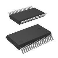
M37542F8FP Renesas Electronics America, M37542F8FP Datasheet - Page 72

M37542F8FP
Manufacturer Part Number
M37542F8FP
Description
IC 740 MCU FLASH 32K 36SSOP
Manufacturer
Renesas Electronics America
Series
740/38000r
Datasheet
1.M37542F8FPU0.pdf
(124 pages)
Specifications of M37542F8FP
Core Processor
740
Core Size
8-Bit
Speed
8MHz
Connectivity
SIO, UART/USART
Peripherals
POR, WDT
Number Of I /o
29
Program Memory Size
32KB (32K x 8)
Program Memory Type
FLASH
Ram Size
1K x 8
Voltage - Supply (vcc/vdd)
2.2 V ~ 5.5 V
Data Converters
A/D 8x10b
Oscillator Type
Internal
Operating Temperature
-20°C ~ 85°C
Package / Case
36-SSOP
Lead Free Status / RoHS Status
Contains lead / RoHS non-compliant
Eeprom Size
-
Available stocks
Company
Part Number
Manufacturer
Quantity
Price
Part Number:
M37542F8FP
Manufacturer:
MIT
Quantity:
20 000
Company:
Part Number:
M37542F8FP#U0
Manufacturer:
TI
Quantity:
109
7542 Group
2. Connection of bypass capacitor across V
Connect an approximately 0.1 µ F bypass capacitor across the V
line and the V
• Connect a bypass capacitor across the V
• Connect a bypass capacitor across the V
• Use lines with a larger diameter than other signal lines for V
• Connect the power source wiring via a bypass capacitor to the
Fig. 91 Bypass capacitor across the V
Rev.3.03
REJ03B0006-0303
at equal length.
with the shortest possible wiring.
line and V
V
SS
pin and the V
CC
N.G.
CC
Jul 11, 2008
line.
V
V
line as follows:
CC
SS
CC
pin.
Page 70 of 117
SS
SS
SS
SS
line and the V
O.K.
V
V
pin and the V
pin and the V
line and V
CC
SS
CC
CC
CC
CC
line
line
pin
pin
SS
SS
3. Wiring to analog input pins
• Connect an approximately 100 Ω to 1 kΩ resistor to an analog
• Connect an approximately 1000 pF capacitor across the Vss pin
<Reason>
Signals which is input in an analog input pin (such as an A/D con-
verter/comparator input pin) are usually output signals from
sensor. The sensor which detects a change of event is installed far
from the printed circuit board with a microcomputer, the wiring to
an analog input pin is longer necessarily. This long wiring func-
tions as an antenna which feeds noise into the microcomputer,
which causes noise to an analog input pin.
Fig. 92 Analog signal line and a resistor and a capacitor
• The analog input pin is connected to the capacitor of a voltage
signal line which is connected to an analog input pin in series.
Besides, connect the resistor to the microcomputer as close as
possible.
and the analog input pin. Besides, connect the capacitor to the
Vss pin as close as possible. Also, connect the capacitor across
the analog input pin and the Vss pin at equal length.
comparator. Accordingly, sufficient accuracy may not be ob-
tained by the charge/discharge current at the time of A/D
conversion when the analog signal source of high-impedance is
connected to an analog input pin. In order to obtain the A/D con-
version result stabilized more, please lower the impedance of an
analog signal source, or add the smoothing capacitor to an ana-
log input pin.
Thermistor
Noise
Note : The resistor is used for dividing
N.G.
resistance with a thermistor.
(Note)
O.K.
Microcomputer
V
Analog
input pin
SS


