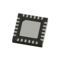
AK5701VNP AKM Semiconductor Inc, AK5701VNP Datasheet - Page 39

AK5701VNP
Manufacturer Part Number
AK5701VNP
Description
IC ADC AUDIO STER 16BIT 24QFN
Manufacturer
AKM Semiconductor Inc
Type
ADCr
Datasheet
1.AK5701VNP.pdf
(64 pages)
Specifications of AK5701VNP
Resolution (bits)
16 b
Sampling Rate (per Second)
7.35k ~ 48k
Data Interface
I²S, Serial
Voltage Supply Source
Analog and Digital
Voltage - Supply
3V
Operating Temperature
-30°C ~ 85°C
Mounting Type
Surface Mount
Package / Case
24-WFQFN Exposed Pad
Lead Free Status / RoHS Status
Lead free / RoHS Compliant
Other names
974-1039-2
AK5701VNP
AK5701VNP
Available stocks
Company
Part Number
Manufacturer
Quantity
Price
Company:
Part Number:
AK5701VNP-L
Manufacturer:
AKM Semiconductor Inc
Quantity:
1 874
Company:
Part Number:
AK5701VNP-L
Manufacturer:
ST
Quantity:
7 190
When writing to the IVL7-0 and IVR7-0 bits continuouslly, the control register should be written in an interval more than
zero crossing timeout. If not, IVL and IVR are not changed since zero crossing counter is reset at every write operation. If
the same register value as the previous write operation is written to IVL and IVR, this write operation is ignored and zero
crossing counter is not reset. Therefore, IVL and IVR can be written in an interval less than zero crossing timeout.
(1) The IVL value becomes the start value if the IVL and IVR are different when the ALC starts. The wait time from
(2) Writing to IVL and IVR registers (18H and 19H) is ignored during ALC operation. After ALC is disabled, the IVOL
■
When power-up, the AK5701 should be reset by bringing the PDN pin = “L”. This ensures that all internal registers reset
to their initial values.
The ADC enters an initialization cycle that starts when the PMADL or PMADR bit is changed from “0” to “1”. The
initialization cycle time is 3088/fs=70.0ms@fs=44.1kHz when HPF1-0 bits are “00”
cycle, the ADC digital data outputs of both channels are forced to a 2’s compliment, “0”. The ADC output reflects the
analog input signal after the initialization cycle is complete.
MS0404-E-02
HPF1 bit
System Reset
ALC bit = “1” to ALC operation start by IVL7-0 bits is at most recovery time (WTM1-0 bits) plus zerocross timeout
period (ZTM1-0 bits).
changes to the last written data by zero crossing or timeout. When ALC is enabled again, ALC bit should be set to “1”
by an interval more than zero crossing timeout period after ALC bit = “0”.
0
0
1
1
HPF0 bit
ALC bit
ALC Status
IVL7-0 bits
IVR7-0 bits
Internal IVL
Internal IVR
0
1
0
1
Table 30. ADC Initialization Cycle (N/A: Not available)
C6H(+20dB)
E1H(+30dB)
3088/fs
1552/fs
Figure 40. IVOL value during ALC operation
784/fs
Cycle
Disable
N/A
(1)
(Recommendation)
fs=44.1kHz
E1(+30dB) --> F1(+36dB)
E1(+30dB) --> F1(+36dB)
70.0ms
35.2ms
17.8ms
- 39 -
N/A
E1H(+30dB)
C6H(+20dB)
Enable
Init Cycle
(Recommendation)
fs=22.05kHz
140.0ms
70.4ms
35.6ms
N/A
(Table
(2)
C6H(+20dB)
E1(+30dB)
Disable
30). During the initialization
(Recommendation)
fs=11.025kHz
280.1ms
140.8ms
71.1ms
N/A
[AK5701]
(default
)
2007/08


