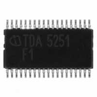
TDA5251 Infineon Technologies, TDA5251 Datasheet - Page 88

TDA5251
Manufacturer Part Number
TDA5251
Description
TXRX FSK/ASK SGL LP TSSOP-38
Manufacturer
Infineon Technologies
Type
Transceiverr
Specifications of TDA5251
Package / Case
38-TSSOP
Frequency
315MHz
Data Rate - Maximum
64kbps
Modulation Or Protocol
ASK, FSK
Applications
RKE, Remote Control Systems
Power - Output
13dBm
Sensitivity
-109dBm
Voltage - Supply
2.1 V ~ 5.5 V
Current - Receiving
9.3mA
Current - Transmitting
14mA
Data Interface
PCB, Surface Mount
Antenna Connector
PCB, Surface Mount
Operating Temperature
-40°C ~ 85°C
Operating Frequency
0.35 MHz
Operating Supply Voltage
2.5 V, 3.3 V, 5 V
Maximum Operating Temperature
+ 85 C
Minimum Operating Temperature
- 40 C
Mounting Style
SMD/SMT
Operating Temperature (min)
-40C
Operating Temperature (max)
85C
Operating Temperature Classification
Industrial
Product Depth (mm)
4.4mm
Product Length (mm)
9.7mm
Operating Supply Voltage (min)
2.1V
Operating Supply Voltage (max)
5.5V
Lead Free Status / RoHS Status
Lead free / RoHS Compliant
Memory Size
-
Lead Free Status / Rohs Status
Compliant
Other names
SP000014554
TDA5251
TDA5251INTR
TDA5251XT
TDA5251
TDA5251INTR
TDA5251XT
Available stocks
Company
Part Number
Manufacturer
Quantity
Price
Company:
Part Number:
TDA5251
Manufacturer:
INFINEON
Quantity:
276
List of Figures
Figure 3-25
Figure 3-26
Figure 3-27
Figure 3-28
Figure 3-29
Figure 3-30
Figure 3-31
Figure 3-32
Figure 3-33
Figure 3-34
Figure 3-35
Figure 4-1
Figure 4-2
Figure 4-3
Figure 4-4
Data Sheet
Peak Detector timing . . . . . . . . . . . . . . . . . . . . . . . . . . . . . . . . . . . . . page
Peak Detector as analog Buffer (v=1) . . . . . . . . . . . . . . . . . . . . . . . . page
Peak detector - power down mode . . . . . . . . . . . . . . . . . . . . . . . . . . page
Power down mode. . . . . . . . . . . . . . . . . . . . . . . . . . . . . . . . . . . . . . . page
Frequency Detection timing in continuous mode . . . . . . . . . . . . . . . page
Frequency Detection timing in Single Shot mode . . . . . . . . . . . . . . . page
Window Counter timing . . . . . . . . . . . . . . . . . . . . . . . . . . . . . . . . . . . page
Example for transmitted Data-structure. . . . . . . . . . . . . . . . . . . . . . . page
3 possible timings . . . . . . . . . . . . . . . . . . . . . . . . . . . . . . . . . . . . . . . page
BER Test Setup. . . . . . . . . . . . . . . . . . . . . . . . . . . . . . . . . . . . . . . . . page
BER supply voltage . . . . . . . . . . . . . . . . . . . . . . . . . . . . . . . . . . . . . . page
I2C Bus Timing . . . . . . . . . . . . . . . . . . . . . . . . . . . . . . . . . . . . . . . . . page
3-wire Bus Timing . . . . . . . . . . . . . . . . . . . . . . . . . . . . . . . . . . . . . . . page
Schematic of the Evaluation Board . . . . . . . . . . . . . . . . . . . . . . . . . . page
Layout of the Evaluation Board . . . . . . . . . . . . . . . . . . . . . . . . . . . . . page
88
TDA5251 F1
Version 1.1
2007-02-26
63
64
65
65
66
66
67
69
70
71
72
78
78
81
82


