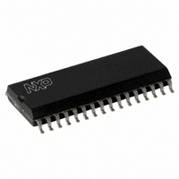
SLRC40001T/OFE,112 NXP Semiconductors, SLRC40001T/OFE,112 Datasheet - Page 106

SLRC40001T/OFE,112
Manufacturer Part Number
SLRC40001T/OFE,112
Description
IC I.CODE SLRC400 READER 32-SOIC
Manufacturer
NXP Semiconductors
Series
I-Coder
Datasheets
1.SLRC40001TOFE112.pdf
(130 pages)
2.SLRC40001TOFE112.pdf
(132 pages)
3.SLRC40001TOFE112.pdf
(101 pages)
Specifications of SLRC40001T/OFE,112
Rf Type
Read Only
Frequency
13.56MHz
Features
ISO15693, ISO18000-3
Package / Case
32-SOIC (0.300", 7.50mm Width)
Product
RFID Readers
Operating Temperature Range
- 25 C to + 85 C
Lead Free Status / RoHS Status
Lead free / RoHS Compliant
Lead Free Status / RoHS Status
Lead free / RoHS Compliant, Lead free / RoHS Compliant
Other names
568-1124-5
935269551112
SLRC400
SLRC41TOFED
935269551112
SLRC400
SLRC41TOFED
- Current page: 106 of 130
- Download datasheet (689Kb)
NWrite
Data
WriteE2
command active
E²PROM
Programming
E2Ready
TxIRq
Philips Semiconductors
I•CODE Reader IC
16.5.1.3 Timing Diagram
The following diagram shows programming of 5 bytes into the E²PROM:
Explanation: It is assumed, that the SL RC400 finds and reads Byte 0 before the µ-Processor is able to write
Byte 1 (t
t
E²PROM starting byte-address is e.g. 4C
following data bytes into the E²PROM input buffer. Copying Byte 3, it detects, that this data byte has to be
programmed at the E²PROM byte-address 4F
automatically starts a programming cycle. In the next turn, Byte 4 will be programmed at the E²PROM byte-
address 50
E²PROM programming activity will be set.
Although all data has been programmed into the E2PROM, the SL RC400 stays in the WriteE2-Command.
Writing further data to the FIFO would lead to further E²PROM programming, continuing at the E²PROM
byte-address 51
16.5.1.4 Error Flags for the WriteE2 Command
Programming is inhibited for the E²PROM blocks 0 (E²PROM’s byte-address 00
these addresses sets the flag AccessErr. No programming cycle is started (for the E²PROM memory
organisation refer to chapter 6.). It is strictly recommended to use only the described E²PROM address area.
prog
= 2.9 ms. In the meantime the µ-Processor stores Byte 1 to Byte 4 to the FIFO buffer. Assuming, that the
prog,del
Write
E2
hex
LSB
. Since this is the last data byte, the flags (E2Ready and TxIRq) that indicate the end of the
Adr
= 300 ns). This causes the SL RC400 to start the programming cycle, which needs about
hex
MSB
Adr
. The command is stopped using the Idle-Command.
Byte0
t
prg,del
Byte1
Figure 16-3: Timing Diagram for E²PROM programming
Byte2
Programming Byte0
t
prog
Byte3
hex
then Byte 0 is stored exactly there. The SL RC400 copies the
hex
Byte4
. Since this is the end of the memory block, the SL RC400
106
Programming Byte1, Byte2, and Byte3
t
prog
Product Specification Rev. 3.1 August 2004
hex
to 0F
hex
Programming Byte4
). Programming to
t
prog
SL RC400
Cmd
Idle
Related parts for SLRC40001T/OFE,112
Image
Part Number
Description
Manufacturer
Datasheet
Request
R
Part Number:
Description:
NXP Semiconductors designed the LPC2420/2460 microcontroller around a 16-bit/32-bitARM7TDMI-S CPU core with real-time debug interfaces that include both JTAG andembedded trace
Manufacturer:
NXP Semiconductors
Datasheet:

Part Number:
Description:
NXP Semiconductors designed the LPC2458 microcontroller around a 16-bit/32-bitARM7TDMI-S CPU core with real-time debug interfaces that include both JTAG andembedded trace
Manufacturer:
NXP Semiconductors
Datasheet:
Part Number:
Description:
NXP Semiconductors designed the LPC2468 microcontroller around a 16-bit/32-bitARM7TDMI-S CPU core with real-time debug interfaces that include both JTAG andembedded trace
Manufacturer:
NXP Semiconductors
Datasheet:
Part Number:
Description:
NXP Semiconductors designed the LPC2470 microcontroller, powered by theARM7TDMI-S core, to be a highly integrated microcontroller for a wide range ofapplications that require advanced communications and high quality graphic displays
Manufacturer:
NXP Semiconductors
Datasheet:
Part Number:
Description:
NXP Semiconductors designed the LPC2478 microcontroller, powered by theARM7TDMI-S core, to be a highly integrated microcontroller for a wide range ofapplications that require advanced communications and high quality graphic displays
Manufacturer:
NXP Semiconductors
Datasheet:
Part Number:
Description:
The Philips Semiconductors XA (eXtended Architecture) family of 16-bit single-chip microcontrollers is powerful enough to easily handle the requirements of high performance embedded applications, yet inexpensive enough to compete in the market for hi
Manufacturer:
NXP Semiconductors
Datasheet:
Part Number:
Description:
The XA-S3 device is a member of Philips Semiconductors? XA(eXtended Architecture) family of high performance 16-bitsingle-chip microcontrollers
Manufacturer:
NXP Semiconductors
Datasheet:

Part Number:
Description:
The NXP BlueStreak LH75401/LH75411 family consists of two low-cost 16/32-bit System-on-Chip (SoC) devices
Manufacturer:
NXP Semiconductors
Datasheet:

Part Number:
Description:
The NXP LPC3130/3131 combine an 180 MHz ARM926EJ-S CPU core, high-speed USB2
Manufacturer:
NXP Semiconductors
Datasheet:

Part Number:
Description:
The NXP LPC3141 combine a 270 MHz ARM926EJ-S CPU core, High-speed USB 2
Manufacturer:
NXP Semiconductors

Part Number:
Description:
The NXP LPC3143 combine a 270 MHz ARM926EJ-S CPU core, High-speed USB 2
Manufacturer:
NXP Semiconductors

Part Number:
Description:
The NXP LPC3152 combines an 180 MHz ARM926EJ-S CPU core, High-speed USB 2
Manufacturer:
NXP Semiconductors

Part Number:
Description:
The NXP LPC3154 combines an 180 MHz ARM926EJ-S CPU core, High-speed USB 2
Manufacturer:
NXP Semiconductors

Part Number:
Description:
Standard level N-channel enhancement mode Field-Effect Transistor (FET) in a plastic package using NXP High-Performance Automotive (HPA) TrenchMOS technology
Manufacturer:
NXP Semiconductors
Datasheet:


