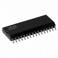
SLRC40001T/OFE,112 NXP Semiconductors, SLRC40001T/OFE,112 Datasheet - Page 115

SLRC40001T/OFE,112
Manufacturer Part Number
SLRC40001T/OFE,112
Description
IC I.CODE SLRC400 READER 32-SOIC
Manufacturer
NXP Semiconductors
Series
I-Coder
Datasheets
1.SLRC40001TOFE112.pdf
(130 pages)
2.SLRC40001TOFE112.pdf
(132 pages)
3.SLRC40001TOFE112.pdf
(101 pages)
Specifications of SLRC40001T/OFE,112
Rf Type
Read Only
Frequency
13.56MHz
Features
ISO15693, ISO18000-3
Package / Case
32-SOIC (0.300", 7.50mm Width)
Product
RFID Readers
Operating Temperature Range
- 25 C to + 85 C
Lead Free Status / RoHS Status
Lead free / RoHS Compliant
Lead Free Status / RoHS Status
Lead free / RoHS Compliant, Lead free / RoHS Compliant
Other names
568-1124-5
935269551112
SLRC400
SLRC41TOFED
935269551112
SLRC400
SLRC41TOFED
- Current page: 115 of 130
- Download datasheet (689Kb)
Philips Semiconductors
I•CODE Reader IC
18.4 Digital Test-Signals
Digital test signals may be routed to pin SIGOUT by setting bit SignalToSIGOUT to 1. A digital test signal
may be selected via the register bits TestDigiSignalSel in Register TestDigiSelect.
The signals selected by a certain TestDigiSignalSel setting is shown in the table below:
If no test signals are used, the value for the TestDigiSel-Register shall be 00
Note: All other values of TestDigiSignalSel are for production test purposes only.
TestDigiSignalSel
E4
D4
C4
D5
C5
F4
96
00
hex
hex
hex
hex
hex
hex
hex
hex
Signal Name
no test signal
int_clock
wr_sync
rd_sync
s_clock
s_valid
s_data
s_coll
Table 18-3: Digital Test Signal Selection
Data received from the label.
Shows with 1, that the signals s_data and s_coll are valid.
Shows with 1, that a collision has been detected in the current bit.
Internal serial clock: during transmission, this is the coder-clock and during
reception this is the receiver clock.
Internal synchronised read signal (derived from the parallel µ-Processor
interface).
Internal synchronised write signal (derived from the parallel µ-Processor
interface).
Internal 13.56 MHz clock.
output as defined by SIGOUTSelect are routed to pin SIGOUT.
115
Product Specification Rev. 3.1 August 2004
Description
hex
.
SL RC400
Related parts for SLRC40001T/OFE,112
Image
Part Number
Description
Manufacturer
Datasheet
Request
R
Part Number:
Description:
NXP Semiconductors designed the LPC2420/2460 microcontroller around a 16-bit/32-bitARM7TDMI-S CPU core with real-time debug interfaces that include both JTAG andembedded trace
Manufacturer:
NXP Semiconductors
Datasheet:

Part Number:
Description:
NXP Semiconductors designed the LPC2458 microcontroller around a 16-bit/32-bitARM7TDMI-S CPU core with real-time debug interfaces that include both JTAG andembedded trace
Manufacturer:
NXP Semiconductors
Datasheet:
Part Number:
Description:
NXP Semiconductors designed the LPC2468 microcontroller around a 16-bit/32-bitARM7TDMI-S CPU core with real-time debug interfaces that include both JTAG andembedded trace
Manufacturer:
NXP Semiconductors
Datasheet:
Part Number:
Description:
NXP Semiconductors designed the LPC2470 microcontroller, powered by theARM7TDMI-S core, to be a highly integrated microcontroller for a wide range ofapplications that require advanced communications and high quality graphic displays
Manufacturer:
NXP Semiconductors
Datasheet:
Part Number:
Description:
NXP Semiconductors designed the LPC2478 microcontroller, powered by theARM7TDMI-S core, to be a highly integrated microcontroller for a wide range ofapplications that require advanced communications and high quality graphic displays
Manufacturer:
NXP Semiconductors
Datasheet:
Part Number:
Description:
The Philips Semiconductors XA (eXtended Architecture) family of 16-bit single-chip microcontrollers is powerful enough to easily handle the requirements of high performance embedded applications, yet inexpensive enough to compete in the market for hi
Manufacturer:
NXP Semiconductors
Datasheet:
Part Number:
Description:
The XA-S3 device is a member of Philips Semiconductors? XA(eXtended Architecture) family of high performance 16-bitsingle-chip microcontrollers
Manufacturer:
NXP Semiconductors
Datasheet:

Part Number:
Description:
The NXP BlueStreak LH75401/LH75411 family consists of two low-cost 16/32-bit System-on-Chip (SoC) devices
Manufacturer:
NXP Semiconductors
Datasheet:

Part Number:
Description:
The NXP LPC3130/3131 combine an 180 MHz ARM926EJ-S CPU core, high-speed USB2
Manufacturer:
NXP Semiconductors
Datasheet:

Part Number:
Description:
The NXP LPC3141 combine a 270 MHz ARM926EJ-S CPU core, High-speed USB 2
Manufacturer:
NXP Semiconductors

Part Number:
Description:
The NXP LPC3143 combine a 270 MHz ARM926EJ-S CPU core, High-speed USB 2
Manufacturer:
NXP Semiconductors

Part Number:
Description:
The NXP LPC3152 combines an 180 MHz ARM926EJ-S CPU core, High-speed USB 2
Manufacturer:
NXP Semiconductors

Part Number:
Description:
The NXP LPC3154 combines an 180 MHz ARM926EJ-S CPU core, High-speed USB 2
Manufacturer:
NXP Semiconductors

Part Number:
Description:
Standard level N-channel enhancement mode Field-Effect Transistor (FET) in a plastic package using NXP High-Performance Automotive (HPA) TrenchMOS technology
Manufacturer:
NXP Semiconductors
Datasheet:


