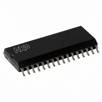
SLRC40001T/OFE,112 NXP Semiconductors, SLRC40001T/OFE,112 Datasheet - Page 112

SLRC40001T/OFE,112
Manufacturer Part Number
SLRC40001T/OFE,112
Description
IC I.CODE SLRC400 READER 32-SOIC
Manufacturer
NXP Semiconductors
Series
I-Coder
Datasheets
1.SLRC40001TOFE112.pdf
(130 pages)
2.SLRC40001TOFE112.pdf
(132 pages)
3.SLRC40001TOFE112.pdf
(101 pages)
Specifications of SLRC40001T/OFE,112
Rf Type
Read Only
Frequency
13.56MHz
Features
ISO15693, ISO18000-3
Package / Case
32-SOIC (0.300", 7.50mm Width)
Product
RFID Readers
Operating Temperature Range
- 25 C to + 85 C
Lead Free Status / RoHS Status
Lead free / RoHS Compliant
Lead Free Status / RoHS Status
Lead free / RoHS Compliant, Lead free / RoHS Compliant
Other names
568-1124-5
935269551112
SLRC400
SLRC41TOFED
935269551112
SLRC400
SLRC41TOFED
- Current page: 112 of 130
- Download datasheet (689Kb)
Philips Semiconductors
I•CODE Reader IC
17.2.3 RECEIVING CIRCUIT
The internal receiving concept of the SL RC400 makes use of both side-bands of the sub-carrier load
modulation of the label response. No external filtering is required.
It is recommended to use the internally generated VMID potential as the input potential of pin RX. This DC
voltage level of VMID has to be coupled to the Rx-pin via R2. To provide a stable DC reference voltage a
capacitance C4 has to be connected between VMID and ground.
Considering the (AC) voltage limits at the Rx-pin the AC voltage divider of R1 + C3 and R2 has to be
designed. Depending on the antenna coil design and the impedance matching the voltage at the antenna coil
varies from antenna design to antenna design. Therefore the recommended way to design the receiving
circuit is to use the given values for R1, R2, and C3 from the above mentioned Application Note, and adjust
the voltage at the Rx-pin by varying R1 within the given limits.
Note: R2 is AC-wise connected to ground (via C4).
17.2.4 ANTENNA COIL
The precise calculation of the antenna coils’ inductance is not practicable but the inductance can be
estimated using the following formula. We recommend designing an antenna either with a circular or
rectangular shape.
l
D
K............... Antenna Shape Factor (K = 1,07 for circular antennas and K = 1,47 for square antennas)
N
ln .............. Natural logarithm function
The actual values of the antenna inductance, resistance, and capacitance at 13.56 MHz depend on
various parameters like:
•
•
•
•
•
Therefore a measurement of those parameters under real life conditions, or at least a rough measurement
and a tuning procedure is recommended to guarantee the optimum performance. For details refer to the
above mentioned application notes.
1
............... Length of one turn of the conductor loop
1
1
............. Diameter of the wire or width of the PCB conductor respectively
............. Number of turns
antenna construction (Type of PCB)
thickness of conductor
distance between the windings
shielding layer
metal or ferrite in the near environment
L nH
1
[
]
= ⋅
2
l cm
1
[
112
] ln
⋅
⎛
⎜
⎝
⎛
⎜
⎝
D
l
1
1
⎞
⎟ −
⎠
Product Specification Rev. 3.1 August 2004
K N
⎞
⎟
⎠
1
1 8
,
SL RC400
Related parts for SLRC40001T/OFE,112
Image
Part Number
Description
Manufacturer
Datasheet
Request
R
Part Number:
Description:
NXP Semiconductors designed the LPC2420/2460 microcontroller around a 16-bit/32-bitARM7TDMI-S CPU core with real-time debug interfaces that include both JTAG andembedded trace
Manufacturer:
NXP Semiconductors
Datasheet:

Part Number:
Description:
NXP Semiconductors designed the LPC2458 microcontroller around a 16-bit/32-bitARM7TDMI-S CPU core with real-time debug interfaces that include both JTAG andembedded trace
Manufacturer:
NXP Semiconductors
Datasheet:
Part Number:
Description:
NXP Semiconductors designed the LPC2468 microcontroller around a 16-bit/32-bitARM7TDMI-S CPU core with real-time debug interfaces that include both JTAG andembedded trace
Manufacturer:
NXP Semiconductors
Datasheet:
Part Number:
Description:
NXP Semiconductors designed the LPC2470 microcontroller, powered by theARM7TDMI-S core, to be a highly integrated microcontroller for a wide range ofapplications that require advanced communications and high quality graphic displays
Manufacturer:
NXP Semiconductors
Datasheet:
Part Number:
Description:
NXP Semiconductors designed the LPC2478 microcontroller, powered by theARM7TDMI-S core, to be a highly integrated microcontroller for a wide range ofapplications that require advanced communications and high quality graphic displays
Manufacturer:
NXP Semiconductors
Datasheet:
Part Number:
Description:
The Philips Semiconductors XA (eXtended Architecture) family of 16-bit single-chip microcontrollers is powerful enough to easily handle the requirements of high performance embedded applications, yet inexpensive enough to compete in the market for hi
Manufacturer:
NXP Semiconductors
Datasheet:
Part Number:
Description:
The XA-S3 device is a member of Philips Semiconductors? XA(eXtended Architecture) family of high performance 16-bitsingle-chip microcontrollers
Manufacturer:
NXP Semiconductors
Datasheet:

Part Number:
Description:
The NXP BlueStreak LH75401/LH75411 family consists of two low-cost 16/32-bit System-on-Chip (SoC) devices
Manufacturer:
NXP Semiconductors
Datasheet:

Part Number:
Description:
The NXP LPC3130/3131 combine an 180 MHz ARM926EJ-S CPU core, high-speed USB2
Manufacturer:
NXP Semiconductors
Datasheet:

Part Number:
Description:
The NXP LPC3141 combine a 270 MHz ARM926EJ-S CPU core, High-speed USB 2
Manufacturer:
NXP Semiconductors

Part Number:
Description:
The NXP LPC3143 combine a 270 MHz ARM926EJ-S CPU core, High-speed USB 2
Manufacturer:
NXP Semiconductors

Part Number:
Description:
The NXP LPC3152 combines an 180 MHz ARM926EJ-S CPU core, High-speed USB 2
Manufacturer:
NXP Semiconductors

Part Number:
Description:
The NXP LPC3154 combines an 180 MHz ARM926EJ-S CPU core, High-speed USB 2
Manufacturer:
NXP Semiconductors

Part Number:
Description:
Standard level N-channel enhancement mode Field-Effect Transistor (FET) in a plastic package using NXP High-Performance Automotive (HPA) TrenchMOS technology
Manufacturer:
NXP Semiconductors
Datasheet:


