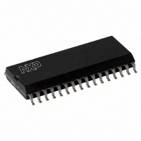
SLRC40001T/OFE,112 NXP Semiconductors, SLRC40001T/OFE,112 Datasheet - Page 91

SLRC40001T/OFE,112
Manufacturer Part Number
SLRC40001T/OFE,112
Description
IC I.CODE SLRC400 READER 32-SOIC
Manufacturer
NXP Semiconductors
Series
I-Coder
Datasheets
1.SLRC40001TOFE112.pdf
(130 pages)
2.SLRC40001TOFE112.pdf
(132 pages)
3.SLRC40001TOFE112.pdf
(101 pages)
Specifications of SLRC40001T/OFE,112
Rf Type
Read Only
Frequency
13.56MHz
Features
ISO15693, ISO18000-3
Package / Case
32-SOIC (0.300", 7.50mm Width)
Product
RFID Readers
Operating Temperature Range
- 25 C to + 85 C
Lead Free Status / RoHS Status
Lead free / RoHS Compliant
Lead Free Status / RoHS Status
Lead free / RoHS Compliant, Lead free / RoHS Compliant
Other names
568-1124-5
935269551112
SLRC400
SLRC41TOFED
935269551112
SLRC400
SLRC41TOFED
- Current page: 91 of 130
- Download datasheet (689Kb)
Philips Semiconductors
I•CODE Reader IC
14.3 Putting the Receiver into Operation
In general, the default settings programmed into the Start Up Initialisation File are suitable to use the
SL RC400 for data communication with I•CODE labels. However, in some environments specific user
settings may achieve better performance.
14.3.1 AUTOMATIC CLOCK-Q CALIBRATION
The quadrature demodulation concept of the receiver generates a phase signal I-clock and a 90° shifted
quadrature signal Q-clock. To achieve an optimum demodulator performance, the Q- and the I-clock have to
have a difference in phase of 90°. After the reset phase of the SL RC400, a calibration procedure is done
automatically. It is possible to have an automatic calibration done at the ending of each Transceive
command. To do so, the ClkQCalib bit has to be configured to a value of 0.
Configuring this bit to a constant value of 1 disables all automatic calibrations except the one after the reset
sequence.
It is also possible to initiate one automatic calibration by software. This is done with a 0 to 1 transition of bit
ClkQCalib.
The details:
Note: The duration of the automatic clock Q calibration is at most 65 oscillator periods which is approx.
4,8µs.
The value of ClkQDelay is proportional to the phase shift between the Q- and the I-clock. The status flag
ClkQ180Deg shows, that the phase shift between the Q- and the I-clock is greater than 180°.
Notes:
•
•
•
The startup configuration file enables an automatically Q-clock calibration after the reset.
While ClkQCalib is 1, no automatic calibration is done. Therefore leaving this bit 1 can be used to
permanently disable the automatic calibration.
It is possible to write data to ClkQDelay via the µ-Processor. The aim could be a disabling of the
automatic calibration and to pre-set the delay by software. But notice, that configuring the delay value by
software requires that bit ClkQCalib has already been set to 1 before and that a time interval of at least
4.8µs has elapsed since then. Each delay value must be written with the ClkQCalib bit set to 1. If
ClkQCalib is 0 the configured delay value will be overwritten by the next interval automatic calibration.
TRANSEIVE command
from reset sequence
calibration impulse
calibration impulse
from ending of
the ClkQCalib bit
91
Product Specification Rev. 3.1 August 2004
a rising edge initiates
a clock Q calibration
SL RC400
Related parts for SLRC40001T/OFE,112
Image
Part Number
Description
Manufacturer
Datasheet
Request
R
Part Number:
Description:
NXP Semiconductors designed the LPC2420/2460 microcontroller around a 16-bit/32-bitARM7TDMI-S CPU core with real-time debug interfaces that include both JTAG andembedded trace
Manufacturer:
NXP Semiconductors
Datasheet:

Part Number:
Description:
NXP Semiconductors designed the LPC2458 microcontroller around a 16-bit/32-bitARM7TDMI-S CPU core with real-time debug interfaces that include both JTAG andembedded trace
Manufacturer:
NXP Semiconductors
Datasheet:
Part Number:
Description:
NXP Semiconductors designed the LPC2468 microcontroller around a 16-bit/32-bitARM7TDMI-S CPU core with real-time debug interfaces that include both JTAG andembedded trace
Manufacturer:
NXP Semiconductors
Datasheet:
Part Number:
Description:
NXP Semiconductors designed the LPC2470 microcontroller, powered by theARM7TDMI-S core, to be a highly integrated microcontroller for a wide range ofapplications that require advanced communications and high quality graphic displays
Manufacturer:
NXP Semiconductors
Datasheet:
Part Number:
Description:
NXP Semiconductors designed the LPC2478 microcontroller, powered by theARM7TDMI-S core, to be a highly integrated microcontroller for a wide range ofapplications that require advanced communications and high quality graphic displays
Manufacturer:
NXP Semiconductors
Datasheet:
Part Number:
Description:
The Philips Semiconductors XA (eXtended Architecture) family of 16-bit single-chip microcontrollers is powerful enough to easily handle the requirements of high performance embedded applications, yet inexpensive enough to compete in the market for hi
Manufacturer:
NXP Semiconductors
Datasheet:
Part Number:
Description:
The XA-S3 device is a member of Philips Semiconductors? XA(eXtended Architecture) family of high performance 16-bitsingle-chip microcontrollers
Manufacturer:
NXP Semiconductors
Datasheet:

Part Number:
Description:
The NXP BlueStreak LH75401/LH75411 family consists of two low-cost 16/32-bit System-on-Chip (SoC) devices
Manufacturer:
NXP Semiconductors
Datasheet:

Part Number:
Description:
The NXP LPC3130/3131 combine an 180 MHz ARM926EJ-S CPU core, high-speed USB2
Manufacturer:
NXP Semiconductors
Datasheet:

Part Number:
Description:
The NXP LPC3141 combine a 270 MHz ARM926EJ-S CPU core, High-speed USB 2
Manufacturer:
NXP Semiconductors

Part Number:
Description:
The NXP LPC3143 combine a 270 MHz ARM926EJ-S CPU core, High-speed USB 2
Manufacturer:
NXP Semiconductors

Part Number:
Description:
The NXP LPC3152 combines an 180 MHz ARM926EJ-S CPU core, High-speed USB 2
Manufacturer:
NXP Semiconductors

Part Number:
Description:
The NXP LPC3154 combines an 180 MHz ARM926EJ-S CPU core, High-speed USB 2
Manufacturer:
NXP Semiconductors

Part Number:
Description:
Standard level N-channel enhancement mode Field-Effect Transistor (FET) in a plastic package using NXP High-Performance Automotive (HPA) TrenchMOS technology
Manufacturer:
NXP Semiconductors
Datasheet:


