LP3907QTLX-VXSS/NOPB National Semiconductor, LP3907QTLX-VXSS/NOPB Datasheet - Page 39
LP3907QTLX-VXSS/NOPB
Manufacturer Part Number
LP3907QTLX-VXSS/NOPB
Description
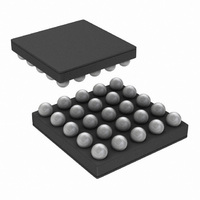
IC REG BUCK SYNC-2 LDO-2 25MSMD
Manufacturer
National Semiconductor
Series
PowerWise®r
Datasheet
1.LP3907SQ-JXQXNOPB.pdf
(46 pages)
Specifications of LP3907QTLX-VXSS/NOPB
Topology
Step-Down (Buck) Synchronous (2), Linear (LDO) (2)
Function
Any Function
Number Of Outputs
4
Frequency - Switching
2.1MHz
Voltage/current - Output 1
1.8V, 1A
Voltage/current - Output 2
3.3V, 600mA
Voltage/current - Output 3
2.8V, 300mA
W/led Driver
No
W/supervisor
No
W/sequencer
Yes
Voltage - Supply
2.8 V ~ 5.5 V
Operating Temperature
-40°C ~ 85°C
Mounting Type
Surface Mount
Package / Case
25-UFBGA
Lead Free Status / RoHS Status
Lead free / RoHS Compliant


Application Notes
ANALOG POWER SIGNAL ROUTING
All power inputs should be tied to the main VDD source (i.e.
battery), unless the user wishes to power it from another
source. (i.e. external LDO output).
The analog VDD inputs power the internal bias and error am-
plifiers, so they should be tied to the main VDD. The analog
VDD inputs must have an input voltage between 2.8 and 5.5V,
as specified in the Electrical Characteristics Section in the
front of the datasheet.
The other V
have inputs lower than 2.8V, as long as it's higher than the
programmed output (+0.3V, to be safe).
The analog and digital grounds should be tied together out-
side of the chip to reduce noise coupling.
COMPONENT SELECTION
Inductors for SW1 and SW2
There are two main considerations when choosing an induc-
tor; the inductor should not saturate and the inductor current
ripple is small enough to achieve the desired output voltage
ripple. Care should be taken when reviewing the different sat-
uration current ratings that are specified by different manu-
facturers. Saturation current ratings are typically specified at
25ºC, so ratings at maximum ambient temperature of the ap-
plication should be requested from the manufacturer.
There are two methods to choose the inductor saturation cur-
rent rating:
Method 1:
The saturation current is greater than the sum of the maxi-
mum load current and the worst case average to peak induc-
tor current. This can be written as follows:
I
I
V
L:
f:
V
Method 2:
A more conservative and recommended approach is to
choose an inductor that has saturation current rating greater
than the maximum current limit of 1250mA for Buck1 and
1750mA for Buck2.
Given a peak-to-peak current ripple (I
to be at least
RIPPLE
OUTMAX
Inductor
L
IN
OUT
SW
:
1,2
:
:
: Maximum load current
Average to peak inductor current
Maximum input voltage to the buck
Min inductor value including worse case tolerances
(30% drop can be considered for method 1)
Minimum switching frequency (1.6 MHz)
Buck Output voltage
IN
Value Unit Description
s (V
2.2
IN
LDO1, V
µH SW1,2 inductor
IN
LDO2, V
PP
IN
1, V
) the inductor needs
IN
Notes
D.C.R. 70mΩ
2) can actually
39
External Capacitors
The regulators on the LP3907 require external capacitors for
regulator stability. These are specifically designed for
portable applications requiring minimum board space and
smallest components. These capacitors must be correctly se-
lected for good performance.
LDO CAPACITOR SELECTION
Input Capacitor
An input capacitor is required for stability. It is recommended
that a 1.0μF capacitor be connected between the LDO input
pin and ground (this capacitance value may be increased
without limit).
This capacitor must be located a distance of not more than
1cm from the input pin and returned to a clean analog ground.
Any good quality ceramic, tantalum, or film capacitor may be
used at the input.
Important: Tantalum capacitors can suffer catastrophic fail-
ures due to surge currents when connected to a low
impedance source of power (like a battery or a very large ca-
pacitor). If a tantalum capacitor is used at the input, it must be
guaranteed by the manufacturer to have a surge current rat-
ing sufficient for the application.
There are no requirements for the ESR (Equivalent Series
Resistance) on the input capacitor, but tolerance and tem-
perature coefficient must be considered when selecting the
capacitor to ensure the capacitance will remain approximately
1.0μF over the entire operating temperature range.
Output Capacitor
The LDOs on the LP3907 are designed specifically to work
with very small ceramic output capacitors. A 0.47µF ceramic
capacitor (temperature types Z5U, Y5V or X7R) with ESR be-
tween 5 mΩ to 500 mΩ, is suitable in the application circuit.
It is also possible to use tantalum or film capacitors at the
device output, C
for reasons of size and cost.
The output capacitor must meet the requirement for the min-
imum value of capacitance and also have an ESR value that
is within the range 5 mΩ to 500 mΩ for stability.
Capacitor Characteristics
The LDOs are designed to work with ceramic capacitors on
the output to take advantage of the benefits they offer. For
capacitance values in the range of 0.47µF to 4.7µF, ceramic
capacitors are the smallest, least expensive and have the
lowest ESR values, thus making them best for eliminating
high frequency noise. The ESR of a typical 1.0µF ceramic
capacitor is in the range of 20mΩ to 40mΩ, which easily
meets the ESR requirement for stability for the LDOs.
For both input and output capacitors, careful interpretation of
the capacitor specification is required to ensure correct device
operation. The capacitor value can change greatly, depend-
ing on the operating conditions and capacitor type.
In particular, the output capacitor selection should take ac-
count of all the capacitor parameters, to ensure that the
specification is met within the application. The capacitance
can vary with DC bias conditions as well as temperature and
frequency of operation. Capacitor values will also show some
decrease over time due to aging. The capacitor parameters
are also dependent on the particular case size, with smaller
sizes giving poorer performance figures in general. As an ex-
ample, below is typical graph comparing different capacitor
case sizes in a Capacitance vs. DC Bias plot.
OUT
(or V
OUT
), but these are not as attractive
www.national.com
Related parts for LP3907QTLX-VXSS/NOPB
Image
Part Number
Description
Manufacturer
Datasheet
Request
R

Part Number:
Description:
IC BUCK SYNC 1.2V/3.3V 24MSMD
Manufacturer:
National Semiconductor
Datasheet:

Part Number:
Description:
National Semiconductor [8-Bit D/A Converter]
Manufacturer:
National Semiconductor
Datasheet:
Part Number:
Description:
National Semiconductor [Media Coprocessor]
Manufacturer:
National Semiconductor
Datasheet:
Part Number:
Description:
Digitally Controlled Tone and Volume Circuit with Stereo Audio Power Amplifier, Microphone Preamp Stage and National 3D Sound
Manufacturer:
National Semiconductor
Datasheet:
Part Number:
Description:
Digitally Controlled Tone and Volume Circuit with Stereo Audio Power Amplifier, Microphone Preamp Stage and National 3D Sound
Manufacturer:
National Semiconductor
Datasheet:
Part Number:
Description:
AC97 Rev 2 Codec with Sample Rate Conversion and National 3D Sound
Manufacturer:
National Semiconductor
Part Number:
Description:
Manufacturer:
National Semiconductor
Datasheet:
Part Number:
Description:
Manufacturer:
National Semiconductor
Datasheet:
Part Number:
Description:
General Purpose, Low Voltage, Low Power, Rail-to-Rail Output Operational Amplifiers
Manufacturer:
National Semiconductor
Datasheet:
Part Number:
Description:
8-bit 20 MSPS flash A/D converter.
Manufacturer:
National Semiconductor
Datasheet:
Part Number:
Description:
Low Noise Quad Operational Amplifier
Manufacturer:
National Semiconductor
Datasheet:
Part Number:
Description:
Quad Differential Line Receivers
Manufacturer:
National Semiconductor
Datasheet:
Part Number:
Description:
Quad High Speed Trapezoidal? Bus Transceiver
Manufacturer:
National Semiconductor
Datasheet:
Part Number:
Description:
Dual Line Receiver
Manufacturer:
National Semiconductor
Datasheet: