LP3907QTLX-VXSS/NOPB National Semiconductor, LP3907QTLX-VXSS/NOPB Datasheet - Page 41
LP3907QTLX-VXSS/NOPB
Manufacturer Part Number
LP3907QTLX-VXSS/NOPB
Description
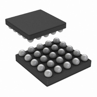
IC REG BUCK SYNC-2 LDO-2 25MSMD
Manufacturer
National Semiconductor
Series
PowerWise®r
Datasheet
1.LP3907SQ-JXQXNOPB.pdf
(46 pages)
Specifications of LP3907QTLX-VXSS/NOPB
Topology
Step-Down (Buck) Synchronous (2), Linear (LDO) (2)
Function
Any Function
Number Of Outputs
4
Frequency - Switching
2.1MHz
Voltage/current - Output 1
1.8V, 1A
Voltage/current - Output 2
3.3V, 600mA
Voltage/current - Output 3
2.8V, 300mA
W/led Driver
No
W/supervisor
No
W/sequencer
Yes
Voltage - Supply
2.8 V ~ 5.5 V
Operating Temperature
-40°C ~ 85°C
Mounting Type
Surface Mount
Package / Case
25-UFBGA
Lead Free Status / RoHS Status
Lead free / RoHS Compliant


I
Both SDA and SCL terminals need to have pullup resistors
connected to VINLDO12 or to the power supply of the I
master. The values of the pull-up resistors (typ.
determined by the capacitance of the bus. Too large of a re-
sistor combined with a given bus capacitance will result in a
rise time that would violate the max. rise time specification. A
too small resistor will result in a contention with the pull-down
transistor on either slave(s) or master.
Operation without I
Operation of the LP3907 without the I
if the system can operate with default values for the LDO and
Buck regulators. (Read below: Factory programmable op-
tions). The I
output values of the LDO and Buck converters.
Factory Programmable Options
The following options are EPROM programmed during final
test of the LP3907. The system designer that needs specific
options is advised to contact the local National Semiconduc-
tor sales office.
The I
The current address for the LLP chip equals 0x60, while the
address for the micro SMD chip is 0x61.
HIGH V
Additional information is provided when the IC is operated at
extremes of V
terms of the Junction temperature and, Buck output ripple
management.
C
C
C
C
2
Enable delay for power on
SW1 ramp speed
SW2 ramp speed
C Pullup Resistor
LDO1
LDO2
SW1
SW2
Factory programmable
2
C Chip ID address is offered as a metal mask option.
IN
Capacitor
HIGH-LOAD OPERATION
options
2
C-less system must rely on the correct default
IN
and regulator loads. These are described in
2
C Interface
Min Value
code 010 (see Control 1
0.47
0.47
10.0
10.0
register section)
2
Current value
C interface is possible
8 mV/µs
8 mV/µs
∼
1.8kΩ) are
Unit
µF
µF
µF
µF
2
C
LDO1 output capacitor
LDO2 output capacitor
SW1 output capacitor
SW2 output capacitor
41
JUNCTION TEMPERATURE
The maximum junction temperature T
IC package.
The following equations demonstrate junction temperature
determination, ambient temperature T
power must be controlled to keep T
T
Total IC power dissipation P
power dissipation of the four regulators plus a minor amount
for chip overhead. Chip overhead is Bias, TSD & LDO analog.
P
[Watts].
Power dissipation of LDO1
P
Power dissipation of LDO2
P
Power dissipation of Buck1
P
Vout
η
Power dissipation of Buck2
P
Vout
η
Where η is the efficiency for the specific condition taken from
efficiency graphs.
J-MAX-OP
1
2
D-MAX
LDO1
LDO2
Buck1
Buck2
= efficiency of buck 1
= efficiency of Buck2
Description
Buck1
Buck2
= (V
= (V
= P
= P
= P
* Iout
* Iout
= T
IN
IN
INLDO1
INLDO2
LDO1
– P
– P
A-MAX
Buck1
Buck2
+ P
OUT
OUT
- V
- Vout
+ (θ
LD02
OUTLDO1
* (1 -η
=
=
* (1 - η
JA
LDO2
+ P
) [ °C/ Watt] * (P
1
Ceramic, 6.3V, X5R
Ceramic, 6.3V, X5R
Ceramic, 6.3V, X5R
Ceramic, 6.3V, X5R
) / η
) * Iout
2
BUCK1
) * Iout
D-MAX
) / η
1
2
Recommended Type
[V*A]
[V*A]
+ P
is the sum of the individual
LDO1
LDO2
J
below this maximum:
BUCK2
J-MAX-OP
[V*A]
[V*A]
A-MAX
D-MAX
+ (0.0001A * V
and Total chip
of 125ºC of the
) [Watts]
www.national.com
IN
)
Related parts for LP3907QTLX-VXSS/NOPB
Image
Part Number
Description
Manufacturer
Datasheet
Request
R

Part Number:
Description:
IC BUCK SYNC 1.2V/3.3V 24MSMD
Manufacturer:
National Semiconductor
Datasheet:

Part Number:
Description:
National Semiconductor [8-Bit D/A Converter]
Manufacturer:
National Semiconductor
Datasheet:
Part Number:
Description:
National Semiconductor [Media Coprocessor]
Manufacturer:
National Semiconductor
Datasheet:
Part Number:
Description:
Digitally Controlled Tone and Volume Circuit with Stereo Audio Power Amplifier, Microphone Preamp Stage and National 3D Sound
Manufacturer:
National Semiconductor
Datasheet:
Part Number:
Description:
Digitally Controlled Tone and Volume Circuit with Stereo Audio Power Amplifier, Microphone Preamp Stage and National 3D Sound
Manufacturer:
National Semiconductor
Datasheet:
Part Number:
Description:
AC97 Rev 2 Codec with Sample Rate Conversion and National 3D Sound
Manufacturer:
National Semiconductor
Part Number:
Description:
Manufacturer:
National Semiconductor
Datasheet:
Part Number:
Description:
Manufacturer:
National Semiconductor
Datasheet:
Part Number:
Description:
General Purpose, Low Voltage, Low Power, Rail-to-Rail Output Operational Amplifiers
Manufacturer:
National Semiconductor
Datasheet:
Part Number:
Description:
8-bit 20 MSPS flash A/D converter.
Manufacturer:
National Semiconductor
Datasheet:
Part Number:
Description:
Low Noise Quad Operational Amplifier
Manufacturer:
National Semiconductor
Datasheet:
Part Number:
Description:
Quad Differential Line Receivers
Manufacturer:
National Semiconductor
Datasheet:
Part Number:
Description:
Quad High Speed Trapezoidal? Bus Transceiver
Manufacturer:
National Semiconductor
Datasheet:
Part Number:
Description:
Dual Line Receiver
Manufacturer:
National Semiconductor
Datasheet: