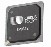
EP9312-CB Cirrus Logic Inc, EP9312-CB Datasheet - Page 775

EP9312-CB
Manufacturer Part Number
EP9312-CB
Description
System-on-Chip Processor
Manufacturer
Cirrus Logic Inc
Series
EP9r
Datasheets
1.EP9307-CRZ.pdf
(824 pages)
2.EP9312-IBZ.pdf
(4 pages)
3.EP9312-CB.pdf
(62 pages)
4.EP9312-CB.pdf
(17 pages)
Specifications of EP9312-CB
Peak Reflow Compatible (260 C)
No
A/d Converter
12 Bits
Leaded Process Compatible
No
No. Of I/o Pins
65
Package / Case
352-BGA
Core Processor
ARM9
Core Size
16/32-Bit
Speed
200MHz
Connectivity
EBI/EMI, EIDE, Ethernet, I²C, IrDA, Keypad/Touchscreen, SPI, UART/USART, USB
Peripherals
AC'97, DMA, I²:S, LCD, LED, MaverickKey, POR, PWM, WDT
Number Of I /o
16
Program Memory Type
ROMless
Ram Size
32K x 8
Voltage - Supply (vcc/vdd)
1.65 V ~ 3.6 V
Data Converters
A/D 8x12b
Oscillator Type
External
Operating Temperature
0°C ~ 70°C
Processor Series
EP93xx
Core
ARM920T
Data Bus Width
32 bit
3rd Party Development Tools
MDK-ARM, RL-ARM, ULINK2
Lead Free Status / RoHS Status
Contains lead / RoHS non-compliant
Eeprom Size
-
Program Memory Size
-
Lead Free Status / Rohs Status
No
Other names
598-1257
Available stocks
Company
Part Number
Manufacturer
Quantity
Price
Part Number:
EP9312-CB
Manufacturer:
CIRRUS
Quantity:
20 000
- EP9307-CRZ PDF datasheet
- EP9312-IBZ PDF datasheet #2
- EP9312-CB PDF datasheet #3
- EP9312-CB PDF datasheet #4
- Current page: 775 of 824
- Download datasheet (13Mb)
DS785UM1
27.2.4 UDMA Operations
27.2.5 Performance Considerations
In a write operation, when the DMA controller writes to IDEMDMADataOut for completing the
DMA transfer, the state machine toggles DIOWn and drives the data onto the DD bus. In a
read operation, when data is filled into IDEMDMADataIn by the host latching in the DD bus at
the DIORn rising edge, the state machine sends the DMA request. The DMA transfer is
completed when the IDEMDMADataIn register is read by the DMA controller. These two
registers should only be written or read by the DMA controller.
The registers IDEDataOut and IDEDataIn are aliased to IDEMDMADataOut and
IDEMDMADataIn during MDMA operations. The host can read IDEDataOut and IDEDataIn
registers at any time. All data transfers are 32-bit wide, with 2 16-bit wide data transfers to or
from the DD bus executed before the next DMA request is sent.
For UDMA operations, DMA commands are set up using PIO operations by the host. There is
a 32-bit, 12-deep output write buffer and a 32-bit, 12-deep input read buffer. These buffers
are circular buffers with head and tail pointers. The state machine set up the necessary
signals including the DMA request to the DMA controller.
In a write operation, when the write buffer has less than 4 entries, a DMA request will be sent
to fill 4 32-bit entries in the buffer. At the same time, the state machine does the handshaking
with the device and sends out the data in 16-bit pieces. Flow control is achieved by the host
through controlling when to toggle HSTROBE and by the device through temporarily
deasserting DDMARDYn.
In a read operation, the state machine does the handshaking and starts to receive data from
the device. When the read buffer has 4 or more entries filled, a DMA request is sent to the
DMA controller. Flow control is achieved by the host through temporarily deasserting
HDMARDYn or by the device through controlling when to toggle DSTROBE.
In both write and read, either the host or the device can terminate the transfer and the state
machine handles the termination handshaking mechanism.
A 16-bit CRC result is always sent from the host to device in both write and read operations
for checking. The CRC registers are “seeded” or pre-loaded with the value of 0x4ABA at the
beginning of the transfer. The “ping-pong” method is used and a “grace” area is provided in
the buffers in case the handshaking required for pausing comes more slowly than the data.
All data transfers are in chunks of four 32-bit words. Pieces of 16-bit wide data to or from the
DD bus are consumed or collected. All data to be transferred through the DMA controller
must be on word boundaries. In case the last chunk contains less than 4 32-bit words, a non-
4-word transfer is allowed.
IDE data transfer performance depends on many factors. All PIO operations are expected to
complete at the normal speed of the IDE interface when configured for the fastest PIO mode.
Payload data transfers will normally use one of the DMA modes. For host read operations the
DMA controller will try to keep the input read buffer empty. For host write operations the DMA
controller will try to keep the output write buffer at least half full. If the DMA Transfer State
Copyright 2007 Cirrus Logic
EP93xx User’s Guide
IDE Interface
27-5
27
Related parts for EP9312-CB
Image
Part Number
Description
Manufacturer
Datasheet
Request
R

Part Number:
Description:
IC ARM920T MCU 200MHZ 352-PBGA
Manufacturer:
Cirrus Logic Inc
Datasheet:

Part Number:
Description:
IC ARM9 SOC UNIVERSAL 352PBGA
Manufacturer:
Cirrus Logic Inc
Datasheet:

Part Number:
Description:
IC ARM920T MCU 200MHZ 352-PBGA
Manufacturer:
Cirrus Logic Inc
Datasheet:

Part Number:
Description:
IC Universal Platform ARM9 SOC Prcessor
Manufacturer:
Cirrus Logic Inc
Datasheet:

Part Number:
Description:
IC Universal Platform ARM9 SOC Prcessor
Manufacturer:
Cirrus Logic Inc
Datasheet:

Part Number:
Description:
Development Kit
Manufacturer:
Cirrus Logic Inc
Datasheet:

Part Number:
Description:
Development Kit
Manufacturer:
Cirrus Logic Inc
Datasheet:

Part Number:
Description:
High-efficiency PFC + Fluorescent Lamp Driver Reference Design
Manufacturer:
Cirrus Logic Inc
Datasheet:

Part Number:
Description:
Development Kit
Manufacturer:
Cirrus Logic Inc
Datasheet:

Part Number:
Description:
Development Kit
Manufacturer:
Cirrus Logic Inc
Datasheet:

Part Number:
Description:
Development Kit
Manufacturer:
Cirrus Logic Inc
Datasheet:

Part Number:
Description:
Development Kit
Manufacturer:
Cirrus Logic Inc
Datasheet:

Part Number:
Description:
Ref Bd For Speakerbar MSA & DSP Products
Manufacturer:
Cirrus Logic Inc


