RFP50N06 Fairchild Semiconductor, RFP50N06 Datasheet - Page 5
RFP50N06
Manufacturer Part Number
RFP50N06
Description
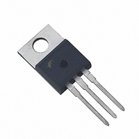
MOSFET N-CH 60V 50A TO-220AB
Manufacturer
Fairchild Semiconductor
Datasheet
1.RFP50N06.pdf
(8 pages)
Specifications of RFP50N06
Fet Type
MOSFET N-Channel, Metal Oxide
Fet Feature
Standard
Rds On (max) @ Id, Vgs
22 mOhm @ 50A, 10V
Drain To Source Voltage (vdss)
60V
Current - Continuous Drain (id) @ 25° C
50A
Vgs(th) (max) @ Id
4V @ 250µA
Gate Charge (qg) @ Vgs
150nC @ 20V
Input Capacitance (ciss) @ Vds
2020pF @ 25V
Power - Max
131W
Mounting Type
Through Hole
Package / Case
TO-220-3 (Straight Leads)
Configuration
Single
Transistor Polarity
N-Channel
Resistance Drain-source Rds (on)
0.022 Ohm @ 10 V
Drain-source Breakdown Voltage
60 V
Gate-source Breakdown Voltage
+/- 20 V
Continuous Drain Current
50 A
Power Dissipation
131000 mW
Maximum Operating Temperature
+ 175 C
Mounting Style
Through Hole
Minimum Operating Temperature
- 55 C
Lead Free Status / RoHS Status
Lead free / RoHS Compliant
Available stocks
Company
Part Number
Manufacturer
Quantity
Price
Company:

Part Number:
RFP50N06
Manufacturer:
FSC
Quantity:
44 920
Company:
Part Number:
RFP50N06
Manufacturer:
FAIRCHILD
Quantity:
3 690
Company:
Part Number:
RFP50N06
Manufacturer:
ST
Quantity:
20 000
Part Number:
RFP50N06
Manufacturer:
FAIRCHILD/仙童
Quantity:
20 000
Company:
Part Number:
RFP50N06LE
Manufacturer:
KA/INTRISII
Quantity:
12 500


©2002 Fairchild Semiconductor Corporation
Typical Performance Curves
Test Circuits and Waveforms
FIGURE 12. CAPACITANCE vs DRAIN TO SOURCE VOLTAGE
VARY t
REQUIRED PEAK I
0V
V
GS
4000
3000
2000
1000
FIGURE 14. UNCLAMPED ENERGY TEST CIRCUIT
0
P
FIGURE 16. SWITCHING TIME TEST CIRCUIT
0
TO OBTAIN
V
t
GS
P
AS
V
5
DS
, DRAIN TO SOURCE VOLTAGE (V)
V
GS
R
10
G
R
GS
C
C
C
OSS
ISS
RSS
15
V
DS
V
I
V
C
C
C
Unless Otherwise Specified (Continued)
AS
DS
GS
ISS
RSS
OSS
DUT
R
DUT
= 0V, f = 1MHz
L
= C
0.01Ω
= C
= C
L
20
GS
GD
DS
+ C
+ C
+
-
+
-
GD
V
GD
V
DD
DD
25
NOTE: Refer to Fairchild Application Notes AN7254 and AN7260.
FIGURE 13. NORMALIZED SWITCHING WAVEFORMS FOR
0
0
0
V
V
60
45
30
15
GS
DS
0
10%
FIGURE 15. UNCLAMPED ENERGY WAVEFORMS
20
V
t
FIGURE 17. SWITCHING WAVEFORMS
DD
d(ON)
90%
I
I
g(REF)
g(ACT)
CONSTANT GATE CURRENT
50%
t
= BV
ON
10%
DSS
t
0.75 BV
0.50 BV
0.25 BV
r
I
AS
R
I
V
g(REF)
PULSE WIDTH
GS
L
t, TIME (µs)
DSS
DSS
DSS
= 1.2Ω
t
P
= 10V
RFG50N06, RFP50N06, RF1S50N06SM Rev. B
= 1.45mA
0.75 BV
0.50 BV
0.25 BV
BV
t
AV
DSS
V
DSS
DSS
DSS
DD
= BV
80
t
d(OFF)
I
I
90%
g(REF)
g(ACT)
DSS
V
t
OFF
DS
50%
t
f
10%
V
10
7.5
5.0
2.5
0
90%
DD
Related parts for RFP50N06
Image
Part Number
Description
Manufacturer
Datasheet
Request
R

Part Number:
Description:
Fairchild Semiconductor [IGBT MODULE]
Manufacturer:
Fairchild Semiconductor
Datasheet:

Part Number:
Description:
Discrete Semiconductor Modules
Manufacturer:
Fairchild Semiconductor
Part Number:
Description:
Discrete Semiconductor Modules
Manufacturer:
Fairchild Semiconductor
Part Number:
Description:
This N-Channel MOSFET is produced using Fairchild Semiconductor’s advanced Power Trench® process
Manufacturer:
Fairchild Semiconductor
Datasheet:
Part Number:
Description:
This N-Channel MOSFET is produced using Fairchild Semiconductor’s advanced Power Trench® process
Manufacturer:
Fairchild Semiconductor
Datasheet:
Part Number:
Description:
This N-Channel MOSFET is produced using Fairchild Semiconductor’s advanced PowerTrench® process
Manufacturer:
Fairchild Semiconductor
Datasheet:
Part Number:
Description:
This N-Channel MOSFET is produced using Fairchild Semiconductor’s advanced PowerTrench® process
Manufacturer:
Fairchild Semiconductor
Datasheet:
Part Number:
Description:
This N-Channel MOSFET is produced using Fairchild Semiconductor’s advanced Power Trench® process
Manufacturer:
Fairchild Semiconductor
Datasheet:
Part Number:
Description:
This N-Channel logic Level MOSFETs are produced using Fairchild Semiconductor‘s advanced Power Trench® process that has been special tailored to minimize the on-state resistance and yet maintain superior switching performance
Manufacturer:
Fairchild Semiconductor
Datasheet:
Part Number:
Description:
This N-Channel MOSFET is produced using Fairchild Semiconductor’s advanced Power Trench® process
Manufacturer:
Fairchild Semiconductor
Datasheet:
Part Number:
Description:
This N-Channel SyncFET™ is produced using Fairchild Semiconductor’s advanced PowerTrench® process
Manufacturer:
Fairchild Semiconductor
Datasheet:
Part Number:
Description:
This N-Channel SyncFET™ is produced using Fairchild Semiconductor’s advanced PowerTrench® process
Manufacturer:
Fairchild Semiconductor
Datasheet:
Part Number:
Description:
This N-Channel SyncFET™ is produced using Fairchild Semiconductor’s advanced PowerTrench® process
Manufacturer:
Fairchild Semiconductor
Datasheet:
Part Number:
Description:
This N-Channel logic Level MOSFETs are produced using Fairchild Semiconductor‘s advanced Power Trench® process that has been special tailored to minimize the on-state resistance and yet maintain superior switching performance
Manufacturer:
Fairchild Semiconductor
Datasheet:
Part Number:
Description:
This N-Channel MOSFET is produced using Fairchild Semiconductor’s advanced Power Trench® process that has been especially tailored to minimize the on-state resistance and yet maintain superior switching performance
Manufacturer:
Fairchild Semiconductor
Datasheet: