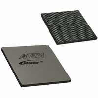
EP1S80B956C7N Altera, EP1S80B956C7N Datasheet - Page 596

EP1S80B956C7N
Manufacturer Part Number
EP1S80B956C7N
Description
IC STRATIX FPGA 80K LE 956-BGA
Manufacturer
Altera
Series
Stratix®r
Datasheet
1.EP1S10F484I6N.pdf
(864 pages)
Specifications of EP1S80B956C7N
Number Of Logic Elements/cells
79040
Number Of Labs/clbs
7904
Total Ram Bits
7427520
Number Of I /o
683
Voltage - Supply
1.425 V ~ 1.575 V
Mounting Type
Surface Mount
Operating Temperature
0°C ~ 85°C
Package / Case
956-BGA
Lead Free Status / RoHS Status
Lead free / RoHS Compliant
Number Of Gates
-
Available stocks
Company
Part Number
Manufacturer
Quantity
Price
- Current page: 596 of 864
- Download datasheet (11Mb)
Finite Impulse Response (FIR) Filters
7–18
Stratix Device Handbook, Volume 2
Inserting zeros between the samples creates reflections of the original
spectrum, thus, a low pass filter is needed to filter out the reflections.
Figure 7–10. Block Diagram Representation of Interpolation
To see how interpolation filters work, consider the Nyquist Sampling
Theorem. This theorem states that the maximum frequency of the input
to be sampled must be smaller than f
frequency, to avoid aliasing. This frequency, f
Nyquist frequency (F
analog to digital converter (ADC), it needs to be low pass filtered using
an analog anti-aliasing filter to prevent aliasing. If the input frequency
spectrum extends close to the Nyquist frequency, then the first alias is also
close to the Nyquist frequency. Therefore, the low pass filter needs to be
very sharp to reject this alias. A very sharp analog filter is hard to design
and manufacture and could increase passband ripple, thereby
compromising system performance.
The solution is to increase the sampling rate of the ADC, so that the new
Nyquist frequency is higher and the spacing between the desired signal
and the alias is also higher. Zero padding as described above increase the
sample rate. This process also known as upsampling (oversampling)
relaxes the roll off requirements of the anti-aliasing filter. Consequently, a
simpler filter achieves alias suppression. A simpler analog filter is easier
to implement, does not compromise system performance, and is also
easier to manufacture.
Similarly, the digital to analog converter (DAC) typically interpolates the
data before the digital to analog conversion. This relaxes the requirement
on the analog low pass filter at the output of the DAC.
The interpolation filter does not need to run at the oversampled
(upsampled) rate of f
are zeros, so they do not contribute to the output.
Figure 7–11
interpolation for a specific case where the original signal spectrum is
limited to 2 MHz and the interpolation factor (I) is 4. The Nyquist
frequency of the upsampled signal must be greater than 8 MHz, and is
chosen to be 9 MHz for this example.
shows the time and frequency domain representation of
sample rate f s
Input
n
s
). Typically, before a signal is sampled using an
I. This is because the extra sample points added
I
s
/2, where f
LPF
s
/2, is also known as the
Output
sample rate I * f s
s
is the sampling
Altera Corporation
September 2004
Related parts for EP1S80B956C7N
Image
Part Number
Description
Manufacturer
Datasheet
Request
R

Part Number:
Description:
CYCLONE II STARTER KIT EP2C20N
Manufacturer:
Altera
Datasheet:

Part Number:
Description:
CPLD, EP610 Family, ECMOS Process, 300 Gates, 16 Macro Cells, 16 Reg., 16 User I/Os, 5V Supply, 35 Speed Grade, 24DIP
Manufacturer:
Altera Corporation
Datasheet:

Part Number:
Description:
CPLD, EP610 Family, ECMOS Process, 300 Gates, 16 Macro Cells, 16 Reg., 16 User I/Os, 5V Supply, 15 Speed Grade, 24DIP
Manufacturer:
Altera Corporation
Datasheet:

Part Number:
Description:
Manufacturer:
Altera Corporation
Datasheet:

Part Number:
Description:
CPLD, EP610 Family, ECMOS Process, 300 Gates, 16 Macro Cells, 16 Reg., 16 User I/Os, 5V Supply, 30 Speed Grade, 24DIP
Manufacturer:
Altera Corporation
Datasheet:

Part Number:
Description:
High-performance, low-power erasable programmable logic devices with 8 macrocells, 10ns
Manufacturer:
Altera Corporation
Datasheet:

Part Number:
Description:
High-performance, low-power erasable programmable logic devices with 8 macrocells, 7ns
Manufacturer:
Altera Corporation
Datasheet:

Part Number:
Description:
Classic EPLD
Manufacturer:
Altera Corporation
Datasheet:

Part Number:
Description:
High-performance, low-power erasable programmable logic devices with 8 macrocells, 10ns
Manufacturer:
Altera Corporation
Datasheet:

Part Number:
Description:
Manufacturer:
Altera Corporation
Datasheet:

Part Number:
Description:
Manufacturer:
Altera Corporation
Datasheet:

Part Number:
Description:
Manufacturer:
Altera Corporation
Datasheet:

Part Number:
Description:
CPLD, EP610 Family, ECMOS Process, 300 Gates, 16 Macro Cells, 16 Reg., 16 User I/Os, 5V Supply, 25 Speed Grade, 24DIP
Manufacturer:
Altera Corporation
Datasheet:


