EP1S80B956C7N Altera, EP1S80B956C7N Datasheet - Page 757
EP1S80B956C7N
Manufacturer Part Number
EP1S80B956C7N
Description
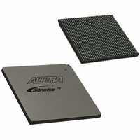
IC STRATIX FPGA 80K LE 956-BGA
Manufacturer
Altera
Series
Stratix®r
Datasheet
1.EP1S10F484I6N.pdf
(864 pages)
Specifications of EP1S80B956C7N
Number Of Logic Elements/cells
79040
Number Of Labs/clbs
7904
Total Ram Bits
7427520
Number Of I /o
683
Voltage - Supply
1.425 V ~ 1.575 V
Mounting Type
Surface Mount
Operating Temperature
0°C ~ 85°C
Package / Case
956-BGA
Lead Free Status / RoHS Status
Lead free / RoHS Compliant
Number Of Gates
-
Available stocks
Company
Part Number
Manufacturer
Quantity
Price


Altera Corporation
July 2005
nCE
nCEO
MSEL
nCONFIG
nSTATUS
CONF_DO
NE
DCLK
DATA0
Table 11–12. Dedicated Configuration Pin Connections During JTAG Configuration
Signal
On all Stratix and Stratix GX devices in the chain,
ground, pulling it low via a resistor, or driving it by some control circuitry. For devices that are also
in multi-device PS, FPP or PPA configuration chains, the
during JTAG configuration or JTAG configured in the same order as the configuration chain.
On all Stratix and Stratix GX devices in the chain,
nCE
These pins must not be left floating. These pins support whichever non-JTAG configuration is used
in production. If only JTAG configuration is used, you should tie both pins to ground.
nCONFIG
to V
Pull to V
nSTATUS
configuration indicates that an error has occurred.
Pull to V
CONF_DONE
JTAG configuration indicates successful configuration.
Should not be left floating. Drive low or high, whichever is more convenient on your board.
Should not be left floating. Drive low or high, whichever is more convenient on your board.
C C
of the next device. See
, pulling high via a resistor, or driven by some control circuitry.
C C
C C
must be driven high through the JTAG programming process. Driven high by connecting
pin should be pulled up to V
via a 10-k resistor. When configuring multiple devices in the same JTAG chain, each
via a 10-k resistor. When configuring multiple devices in the same JTAG chain, each
pin should be pulled up to V
Stratix and Stratix GX devices have dedicated JTAG pins. You can
perform JTAG testing on Stratix and Stratix GX devices before and after,
but not during configuration. The chip-wide reset and output enable pins
on Stratix and Stratix GX devices do not affect JTAG boundary-scan or
programming operations. Toggling these pins does not affect JTAG
operations (other than the usual boundary-scan operation).
When designing a board for JTAG configuration of Stratix and Stratix GX
devices, you should consider the regular configuration pins.
shows how you should connect these pins during JTAG configuration.
JTAG Programming & Configuration of Multiple Devices
When programming a JTAG device chain, one JTAG-compatible header,
such as the ByteBlasterMV header, is connected to several devices. The
number of devices in the JTAG chain is limited only by the drive capacity
of the download cable. However, when more than five devices are
connected in a JTAG chain, Altera recommends buffering the TCK, TDI,
and TMS pins with an on-board buffer.
nCE
pin description above.
C C
individually.
C C
Description
individually.
nCE
nCEO
nSTATUS
Configuring Stratix & Stratix GX Devices
should be driven low by connecting it to
can be left floating or connected to the
nCE
CONF_DONE
Stratix Device Handbook, Volume 2
pins should be connected to GND
pulling low in the middle of JTAG
going high at the end of
Table 11–12
11–39
Related parts for EP1S80B956C7N
Image
Part Number
Description
Manufacturer
Datasheet
Request
R

Part Number:
Description:
CYCLONE II STARTER KIT EP2C20N
Manufacturer:
Altera
Datasheet:


Part Number:
Description:
CPLD, EP610 Family, ECMOS Process, 300 Gates, 16 Macro Cells, 16 Reg., 16 User I/Os, 5V Supply, 35 Speed Grade, 24DIP
Manufacturer:
Altera Corporation
Datasheet:
Part Number:
Description:
CPLD, EP610 Family, ECMOS Process, 300 Gates, 16 Macro Cells, 16 Reg., 16 User I/Os, 5V Supply, 15 Speed Grade, 24DIP
Manufacturer:
Altera Corporation
Datasheet:
Part Number:
Description:
Manufacturer:
Altera Corporation
Datasheet:
Part Number:
Description:
CPLD, EP610 Family, ECMOS Process, 300 Gates, 16 Macro Cells, 16 Reg., 16 User I/Os, 5V Supply, 30 Speed Grade, 24DIP
Manufacturer:
Altera Corporation
Datasheet:
Part Number:
Description:
High-performance, low-power erasable programmable logic devices with 8 macrocells, 10ns
Manufacturer:
Altera Corporation
Datasheet:
Part Number:
Description:
High-performance, low-power erasable programmable logic devices with 8 macrocells, 7ns
Manufacturer:
Altera Corporation
Datasheet:
Part Number:
Description:
Classic EPLD
Manufacturer:
Altera Corporation
Datasheet:
Part Number:
Description:
High-performance, low-power erasable programmable logic devices with 8 macrocells, 10ns
Manufacturer:
Altera Corporation
Datasheet:
Part Number:
Description:
Manufacturer:
Altera Corporation
Datasheet:
Part Number:
Description:
Manufacturer:
Altera Corporation
Datasheet:
Part Number:
Description:
Manufacturer:
Altera Corporation
Datasheet:
Part Number:
Description:
CPLD, EP610 Family, ECMOS Process, 300 Gates, 16 Macro Cells, 16 Reg., 16 User I/Os, 5V Supply, 25 Speed Grade, 24DIP
Manufacturer:
Altera Corporation
Datasheet: