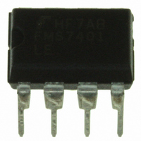
FMS7401LEN Fairchild Semiconductor, FMS7401LEN Datasheet - Page 49

FMS7401LEN
Manufacturer Part Number
FMS7401LEN
Description
IC CTRLR POWER DGTL EEPROM 8DIP
Manufacturer
Fairchild Semiconductor
Datasheet
1.FMS7401LVN.pdf
(81 pages)
Specifications of FMS7401LEN
Applications
Digital Power Controller
Core Processor
8-Bit
Program Memory Type
EEPROM (1 kB)
Ram Size
64 x 8
Number Of I /o
6
Voltage - Supply
2.7 V ~ 3.6 V
Operating Temperature
-40°C ~ 85°C
Mounting Type
Through Hole
Package / Case
8-DIP (0.300", 7.62mm)
Mounting Style
Through Hole
Lead Free Status / RoHS Status
Lead free / RoHS Compliant
Interface
-
Controller Series
-
Lead Free Status / Rohs Status
Lead free / RoHS Compliant
Other names
FMS7401LEN_NL
FMS7401LEN_NL
FMS7401LEN_NL
Available stocks
Company
Part Number
Manufacturer
Quantity
Price
Company:
Part Number:
FMS7401LEN14
Manufacturer:
Rohm
Quantity:
21 626
10.1.6 Interrupt Handling
When an interrupt is recognized, the current instruction completes its execution. The return address (the current value in the
program counter, PC) is pushed onto the stack, the global interrupt (G) mask of the status register (SR) is cleared, and execu-
tion continues at the address specified by the respective interrupt vector (see
cycles to complete. The interrupt vector contains the address of the software’s interrupt service routine (ISR). Initially, the ISR
may save (if necessary) the status register’s contents. Software, however, cannot restore SR using the traditional microcontrol-
ler methods. Just before ending the ISR, software may restore the contents of SR by using only the special inherent instructions
(e.g. SC, RC and LDC) or specially defined software routines since all SR bits except for G are read only when using direct,
indirect, or indexed instructions (e.g. LD , ST, RBIT or SBIT). Upon exiting the ISR, software must clear the appropriate
triggering pending flag and execute a return-from-interrupt (RETI) instruction. The RETI instruction pulls the saved return
address off the stack in reverse order restoring PC and setting G of SR to one. Instruction execution resumes at the restored the
program counter address.
The microcontroller core is capable of supporting five interrupts. Four are maskable through G of the SR and the fifth (software
interrupt) is not inhibited by G (see
INTR instruction is executed, the microcontroller core will interrupt whether G is set or not. The INTR interrupt is executed in
the same manner as the other maskable interrupts where PC is stacked and G is cleared. This means, if G was enabled prior to
the software interrupt the RETI instruction must be used to return from interrupt in order to restore G to one. However, if G
was not enabled prior to the software interrupt the RET instruction must be used.
In the case of simultaneous multiple interrupts, the microcontroller core prioritizes the interrupts. See
service priority sequence.
REV. 1.0.3 1/24/05
PRODUCT SPECIFICATION
PWM T1
INTR
ADC
MIW
T0
Interrupt
Pending
WKPND
T1PND
T0PND
Flags
APND
Figure
T1EN
17). The execution of the INTR instruction generates a software interrupt. Once the
Interrupt Enable Bits
T0INT
Figure 17. Basic Interrupt Structure
EN
WKINT
EN
AINT
EN
Table
Global Interrupt
30). This process takes five instruction
Enable
G
Table 23
for the interrupt
FMS7401L
Interrupt
49


