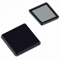
AD9991KCP Analog Devices Inc, AD9991KCP Datasheet - Page 2

AD9991KCP
Manufacturer Part Number
AD9991KCP
Description
IC CCD SIGNAL PROCESSOR 56-LFCSP
Manufacturer
Analog Devices Inc
Type
CCD Signal Processor, 10-Bitr
Datasheet
1.AD9991KCPZRL.pdf
(60 pages)
Specifications of AD9991KCP
Rohs Status
RoHS non-compliant
Input Type
Logic
Output Type
Logic
Interface
3-Wire Serial
Mounting Type
Surface Mount
Package / Case
56-LFCSP
Analog Front End Type
CCD
Analog Front End Category
Video
Interface Type
Serial (3-Wire)
Input Voltage Range
0.5V
Operating Supply Voltage (min)
2.7V
Operating Supply Voltage (typ)
3V
Operating Supply Voltage (max)
3.6V
Resolution
10b
Number Of Adc's
1
Power Supply Type
Analog/Digital
Operating Temp Range
-20C to 85C
Operating Temperature Classification
Commercial
Mounting
Surface Mount
Pin Count
56
Package Type
LFCSP EP
Number Of Channels
1
Current - Supply
-
Lead Free Status / RoHS Status
Not Compliant
Available stocks
Company
Part Number
Manufacturer
Quantity
Price
Company:
Part Number:
AD9991KCP
Manufacturer:
ADI
Quantity:
246
Company:
Part Number:
AD9991KCPZ
Manufacturer:
ADI
Quantity:
244
Company:
Part Number:
AD9991KCPZ-RL
Manufacturer:
FUJISU
Quantity:
4 000
TABLE OF CONTENTS
SPECIFICATIONS ............................................................... 3
ABSOLUTE MAXIMUM RATINGS ..................................... 5
PACKAGE THERMAL CHARACTERISTICS ...................... 5
ORDERING GUIDE ............................................................. 5
PIN CONFIGURATION ....................................................... 6
PIN FUNCTION DESCRIPTIONS....................................... 6
TERMINOLOGY .................................................................. 7
EQUIVALENT CIRCUITS.................................................... 7
TYPICAL PERFORMANCE CHARACTERISTICS ............. 8
SYSTEM OVERVIEW............................................................ 9
PRECISION TIMING HIGH SPEED TIMING
GENERATION .................................................................... 10
HORIZONTAL CLAMPING AND BLANKING ................. 13
HORIZONTAL TIMING SEQUENCE EXAMPLE ............. 15
VERTICAL TIMING GENERATION ................................. 16
AD9991
Timing Specifi cations........................................................... 5
Timing Resolution ............................................................. 10
Vertical Pattern Groups ...................................................... 17
Vertical Sequences.............................................................. 18
Vertical Sensor Gate (Shift Gate) Patterns........................... 22
Analog Specifi cations ........................................................... 4
Digital Specifi cations .......................................................... 3
High Speed Clock Programmability.................................... 10
H-Driver and RG Outputs ................................................. 11
Digital Data Outputs ........................................................ 11
Individual CLPOB and PBLK Patterns .............................. 13
Individual HBLK Patterns ................................................. 13
Generating Special HBLK Patterns .................................... 14
Generating HBLK Line Alteration ..................................... 14
Complete Field: Combining V-Sequences ........................... 19
Generating Line Alternation for V-Sequence and HBLK...... 20
Second V-Pattern Group during VSG Active Line................ 20
Sweep Mode Operation...................................................... 21
Multiplier Mode ................................................................ 21
MODE Register ................................................................ 23
–2–
VERTICAL TIMING EXAMPLE ....................................... 24
SHUTTER TIMING CONTROL ........................................ 26
EXPOSURE AND READOUT EXAMPLE.......................... 30
ANALOG FRONT END DESCRIPTION
POWER-UP AND SYNCHRONIZATION........................... 33
STANDBY MODE OPERATION ........................................ 34
CIRCUIT LAYOUT INFORMATION................................. 36
SERIAL INTERFACE TIMING........................................... 37
COMPLETE LISTING OF REGISTER BANK 1 ............... 40
COMPLETE LISTING OF REGISTER BANK 2 ............... 43
OUTLINE DIMENSIONS.................................................. 59
VSUB Control ................................................................... 28
TRIGGER Register Limitations ......................................... 29
Variable Gain Amplifi er .................................................... 31
AND OPERATION ......................................................... 31
A/D Converter .................................................................. 31
Important Note about Signal Polarities ............................... 24
Normal Shutter Operation ................................................. 26
High Precision Shutter Operation....................................... 26
Low Speed Shutter Operation ............................................ 26
SUBCK Suppression ......................................................... 27
Readout after Exposure...................................................... 27
Using the TRIGGER Register ............................................ 27
MSHUT and STROBE Control ........................................ 28
DC Restore ..................................................................... 31
Correlated Double Sampler............................................... 31
Optical Black Clamp......................................................... 32
Digital Data Outputs ......................................................... 32
Recommended Power-Up Sequence for Master Mode......... 33
Generating Software SYNC without
SYNC during Master Mode Operation............................... 34
Power-Up and Synchronization in Slave Mode.................... 34
Register Address Banks 1 and 2.......................................... 38
Updating of New Register Values........................................ 39
External SYNC Signal ................................................... 33
REV. 0


