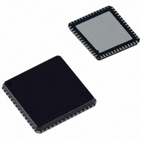
AD9991KCP Analog Devices Inc, AD9991KCP Datasheet - Page 37

AD9991KCP
Manufacturer Part Number
AD9991KCP
Description
IC CCD SIGNAL PROCESSOR 56-LFCSP
Manufacturer
Analog Devices Inc
Type
CCD Signal Processor, 10-Bitr
Datasheet
1.AD9991KCPZRL.pdf
(60 pages)
Specifications of AD9991KCP
Rohs Status
RoHS non-compliant
Input Type
Logic
Output Type
Logic
Interface
3-Wire Serial
Mounting Type
Surface Mount
Package / Case
56-LFCSP
Analog Front End Type
CCD
Analog Front End Category
Video
Interface Type
Serial (3-Wire)
Input Voltage Range
0.5V
Operating Supply Voltage (min)
2.7V
Operating Supply Voltage (typ)
3V
Operating Supply Voltage (max)
3.6V
Resolution
10b
Number Of Adc's
1
Power Supply Type
Analog/Digital
Operating Temp Range
-20C to 85C
Operating Temperature Classification
Commercial
Mounting
Surface Mount
Pin Count
56
Package Type
LFCSP EP
Number Of Channels
1
Current - Supply
-
Lead Free Status / RoHS Status
Not Compliant
Available stocks
Company
Part Number
Manufacturer
Quantity
Price
Company:
Part Number:
AD9991KCP
Manufacturer:
ADI
Quantity:
246
Company:
Part Number:
AD9991KCPZ
Manufacturer:
ADI
Quantity:
244
Company:
Part Number:
AD9991KCPZ-RL
Manufacturer:
FUJISU
Quantity:
4 000
SERIAL INTERFACE TIMING
All of the internal registers of the AD9991 are accessed through
a 3-wire serial interface. Each register consists of an 8-bit address
and a 24-bit data-word. Both the 8-bit address and 24-bit data-
word are written starting with the LSB. To write to each register,
a 32-bit operation is required, as shown in Figure 40a. Although
many registers are fewer than 24 bits wide, all 24 bits must be
written for each register. For example, if the register is only 10
bits wide, the upper 14 bits are don’t cares and may be fi lled with
0s during the serial write operation. If fewer than 24 bits are writ-
ten, the register will not be updated with new data.
REV. 0
SDATA
SCK
SL
SDATA
NOTES
1. MULTIPLE SEQUENTIAL REGISTERS MAY BE LOADED CONTINUOUSLY.
2. THE FIRST (LOWEST ADDRESS) REGISTER ADDRESS IS WRITTEN, FOLLOWED BY MULTIPLE 24-BIT DATA-WORDS.
3. THE ADDRESS WILL AUTOMATICALLY INCREMENT WITH EACH 24-BIT DATA-WORD (ALL 24 BITS MUST BE WRITTEN).
4. SL IS HELD LOW UNTIL THE LAST DESIRED REGISTER HAS BEEN LOADED.
SCK
SL
A0
1
NOTES
1. SDATA BITS ARE LATCHED ON SCK RISING EDGES. SCK MAY IDLE HIGH OR LOW IN BETWEEN WRITE OPERATIONS.
2. ALL 32 BITS MUST BE WRITTEN: 8 BITS FOR ADDRESS AND 24 BITS FOR DATA.
3. IF THE REGISTER LENGTH IS <24 BITS, “DON’T CARE” BITS MUST BE USED TO COMPLETE THE 24-BIT DATA LENGTH.
4. NEW DATA VALUES ARE UPDATED IN THE SPECIFIED REGISTER LOCATION AT DIFFERENT TIMES, DEPENDING ON THE
PARTICULAR REGISTER WRITTEN TO. SEE THE REGISTER UPDATES SECTION FOR MORE INFORMATION.
A1
A0
2
1
t
A2
DS
A1
t
3
LS
2
A3
A2
4
8-BIT ADDRESS
3
A4
A3
5
4
A5
Figure 40b. Continuous Serial Write Operation
t
A4
DH
6
5
A6
A5
7
Figure 40a. Serial Write Operation
6
A7
A6
8
7
D0
A7
9
8
DATA FOR STARTING
REGISTER ADDRESS
D1
10
D0
9
–37–
...
D1
...
...
10
D2
Figure 40b shows a more effi cient way to write to the registers,
using the AD9991’s address auto-increment capability. Using
this method, the lowest desired address is written fi rst, followed
by multiple 24-bit data-words. Each new 24-bit data-word will
automatically be written to the next highest register address. By
eliminating the need to write each 8-bit address, faster register
loading is achieved. Continuous write operations may be used
starting with any register location, and may be used to write to as
few as two registers, or as many as the entire register space.
11
D22
31
D3
24-BIT DATA
12
D23
32
...
...
...
D0
33
D1
REGISTER ADDRESS
D21
34
DATA FOR NEXT
30
D22 D23
t
...
...
...
LH
31
32
D22 D23
55
56
D0
57
D1
58
D2
AD9991
59
...
...
...


