GRM1885C1H101J Murata, GRM1885C1H101J Datasheet - Page 144
GRM1885C1H101J
Manufacturer Part Number
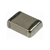
GRM1885C1H101J
Description
Manufacturer
Murata
Datasheet
1.GRM1885C1H101J.pdf
(220 pages)
Specifications of GRM1885C1H101J
Capacitance
100pF
Tolerance (+ Or -)
5%
Voltage
50VDC
Temp Coeff (dielectric)
C0G
Operating Temp Range
-55C to 125C
Mounting Style
Surface Mount
Package / Case
0603
Construction
SMT Chip
Case Style
Ceramic Chip
Failure Rate
Not Required
Wire Form
Not Required
Product Length (mm)
1.6mm
Product Depth (mm)
0.8mm
Product Height (mm)
0.8mm
Product Diameter (mm)
Not Requiredmm
Dc
07+
Lead Free Status / Rohs Status
Compliant
Available stocks
Company
Part Number
Manufacturer
Quantity
Price
Company:

Part Number:
GRM1885C1H101JA01D
Manufacturer:
MURATA
Quantity:
640 000
Company:
Part Number:
GRM1885C1H101JA01D
Manufacturer:
MURATA
Quantity:
208 000
Company:
Part Number:
GRM1885C1H101JA01J
Manufacturer:
MURATA
Quantity:
170 000


8
!Note
• This PDF catalog is downloaded from the website of Murata Manufacturing co., ltd. Therefore, it’s specifications are subject to change or our products in it may be discontinued without advance notice. Please check with our
• This PDF catalog has only typical specifications because there is no space for detailed specifications. Therefore, please approve our product specifications or transact the approval sheet for product specifications before ordering.
sales representatives or product engineers before ordering.
!Note
142
3. Applied Voltage
1. Do not apply a voltage to the capacitor that exceeds the
4. Applied Voltage and Self-heating Temperature
1. When the capacitor is used in a high-frequency voltage,
!Caution
!Caution
rated voltage as called-out in the specifications.
1-1. Applied voltage between the terminals of a capacitor
1-2. Influence of overvoltage
pulse voltage, application, be sure to take into account
self-heating may be caused by resistant factors of the
capacitor.
1-1. The load should be contained to the level such that
Continued from the preceding page.
• Please read rating and !CAUTION (for storage, operating, rating, soldering, mounting and handling) in this catalog to prevent smoking and/or burning, etc.
• This catalog has only typical specifications because there is no space for detailed specifications. Therefore, please approve our product specifications or transact the approval sheet for product specifications before ordering.
shall be less than or equal to the rated voltage.
Typical Voltage Applied to the DC Capacitor
(E: Maximum possible applied voltage.)
(1) When AC voltage is superimposed on DC voltage,
(2) Abnormal voltages (surge voltage, static
Overvoltage that is applied to the capacitor may
result in an electrical short circuit caused by the
breakdown of the internal dielectric layers .
The time duration until breakdown depends on the
applied voltage and the ambient temperature.
when measuring at atomospheric temperature of
25 C, the product's self-heating remains below 20 C
and surface temperature of the capacitor in the
actual circuit remains wiyhin the maximum operating
temperature.
the zero-to-peak voltage shall not exceed the
rated DC voltage.
When AC voltage or pulse voltage is applied, the
peak-to-peak voltage shall not exceed the rated
DC voltage.
electricity, pulse voltage, etc.) shall not exceed
the rated DC voltage.
E
DC Voltage
0
DC Voltage+AC
E
0
E
AC Voltage
0
Continued on the following page.
Pulse Voltage
E
0
C02E.pdf
09.9.18
Related parts for GRM1885C1H101J
Image
Part Number
Description
Manufacturer
Datasheet
Request
R


Part Number:
Description:
Murata Microblower 20x20 DCDC Driver Board - Samples Only
Manufacturer:
Murata
Part Number:
Description:
357-036-542-201 CARDEDGE 36POS DL .156 BLK LOPRO
Manufacturer:
Murata
Datasheet:
Part Number:
Description:
Manufacturer:
Murata
Datasheet:
Part Number:
Description:
Manufacturer:
Murata
Datasheet:
Part Number:
Description:
Manufacturer:
Murata
Datasheet:
Part Number:
Description:
Manufacturer:
Murata
Datasheet:
Part Number:
Description:
Manufacturer:
Murata
Datasheet:
Part Number:
Description:
Manufacturer:
Murata
Datasheet:
Part Number:
Description:
Manufacturer:
Murata
Datasheet:
Part Number:
Description:
BLM21BD751SN1On-Board Type (DC) EMI Suppression Filters
Manufacturer:
Murata
Datasheet:
Part Number:
Description:
BLM15AG100SN1On-Board Type (DC) EMI Suppression Filters
Manufacturer:
Murata
Datasheet:
Part Number:
Description:
NFE31PT222Z1E9On-Board Type (DC) EMI Suppression Filters
Manufacturer:
Murata
Datasheet:
Part Number:
Description:
Chip Coil
Manufacturer:
Murata
Datasheet: