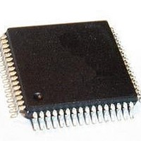
PSB 2132 H V2.2 Infineon Technologies, PSB 2132 H V2.2 Datasheet - Page 28

PSB 2132 H V2.2
Manufacturer Part Number
PSB 2132 H V2.2
Description
IC CODEC FILTER 2CHAN MQFP-64
Manufacturer
Infineon Technologies
Series
SICOFI®r
Datasheet
1.PSB_2132_H_V2.2.pdf
(69 pages)
Specifications of PSB 2132 H V2.2
Package / Case
64-QFP
Function
CODEC Filter
Interface
IOM-2 PCM, SPI
Number Of Circuits
2
Voltage - Supply
5V
Current - Supply
18mA
Power (watts)
90mW
Mounting Type
Surface Mount
Includes
Level Metering Function, Tone Generation
Number Of Adc Inputs
2
Number Of Dac Outputs
2
Interface Type
Serial
Operating Supply Voltage
5 V
Maximum Operating Temperature
+ 70 C
Mounting Style
SMD/SMT
Minimum Operating Temperature
0 C
Number Of Channels
2
Snr
35.4 dB
Supply Current
40 mA
Lead Free Status / RoHS Status
Lead free / RoHS Compliant
Operating Temperature
-
Lead Free Status / RoHS Status
Lead free / RoHS Compliant, Lead free / RoHS Compliant
Other names
PSB2132HV2.2XT
SP000007696
SP000007696
Hardware Reference Manual
4.2.8.2
The Group Delay Distortion in transmit and receive direction will stay within the limits
shown in Table 11. Group Delay Distortion values are referenced to the minimum value
of Group Delay (T
Table 11
4.2.9
Table 12
Table 13
Frequency
500 Hz to 600 Hz
600 Hz to 1.0 kHz
1.0 kHz to 2.6 kHz
2.6 kHz to 3.0 kHz
Parameter
A-Law, psophometric (
µ-Law, C-message (
Parameter
A-Law, psophometric (idle code + 0)
µ-Law, C-message (idle code + 0)
Group Delay Distortion with Frequency
Noise
Group Delay Distortion with Frequency
Idle Channel Noise in Transmit Direction
Idle Channel Noise in Receive Direction
G
min).
V
Symbol
IN
V
= 0 V)
IN
t
t
t
t
G
G
G
G
= 0 V)
min. typ.
Limit Values
19
Symbol
Symbol
N
N
N
N
max.
300
150
100
300
RP
RC
TP
TC
Unit
min.
min.
µs
µs
µs
µs
Limit Values
Limit Values
0 dBm0 input signal level,
reference point is at T
Operational Description
typ.
typ.
–85
Test Conditions
5
max.
–66.0
19.0
max.
–77.0
13.0
PSB 2132
2001-02-20
dBm0p
dBrnc0
dBm0p
dBrnc0
Unit
Unit
G
min.


