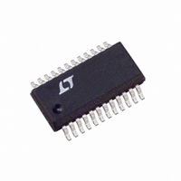
LTC1702IGN#TR Linear Technology, LTC1702IGN#TR Datasheet - Page 12

LTC1702IGN#TR
Manufacturer Part Number
LTC1702IGN#TR
Description
IC REG SW DUAL SYNC 2PH 24SSOP
Manufacturer
Linear Technology
Series
PolyPhase®r
Type
Step-Down (Buck)r
Datasheet
1.LTC1702CGN.pdf
(36 pages)
Specifications of LTC1702IGN#TR
Internal Switch(s)
No
Synchronous Rectifier
Yes
Number Of Outputs
2
Current - Output
1A, 25A
Frequency - Switching
550kHz
Voltage - Input
3 ~ 7 V
Operating Temperature
-40°C ~ 85°C
Mounting Type
Surface Mount
Package / Case
24-SSOP
Lead Free Status / RoHS Status
Contains lead / RoHS non-compliant
Voltage - Output
-
Power - Output
-
Available stocks
Company
Part Number
Manufacturer
Quantity
Price
APPLICATIONS
LTC1702
SHUTDOWN/SOFT-START
Each half of the LTC1702 has a RUN/SS pin. The RUN/SS
pins perform two functions: when pulled to ground, each
shuts down its half of the LTC1702, and each acts as a
conventional soft-start pin, enforcing a maximum duty
cycle limit proportional to the voltage at RUN/SS. An
internal 3.5µA current source pull-up is connected to each
RUN/SS pin, allowing a soft-start ramp to be generated
with a single external capacitor to ground. The 3.5µA
current sources are active even when the LTC1702 is shut
down, ensuring the device will start when any external
pull-down at RUN/SS is released. Either side can be shut
down without affecting the operation of the other side. If
both sides are shut down at the same time, the LTC1702
goes into a micropower sleep mode, and quiescent cur-
rent drops below 100µA. Entering sleep mode also resets
the FAULT latch, if it was set.
Each RUN/SS pin shuts down its half of the LTC1702 when
it falls below about 0.5V. Between 0.5V and about 1V, that
half is active, but the maximum duty cycle is limited to
12
U
V
RUN/SS
INFORMATION
V
OUT
U
0V
5V
0V
Figure 4. Soft-Start Operation in Start-Up and Current Limit
LTC1702 ENABLED
RUN/SS CONTROLS
W
DUTY CYCLE
0.55V
1.0V
START-UP
2.5V
U
COMP CONTROLS DUTY CYCLE
4.5V
MIN COMPARATOR ENABLED
NORMAL OPERATION
10%. The maximum duty cycle limit increases linearly
between 1V and 2.5V, reaching its final value of 90% when
RUN/SS is above 2.5V. Somewhere before this point, the
feedback amplifier will assume control of the loop and the
output will come into regulation. When RUN/SS rises to
0.5V below V
and the LTC1702 is in full operation (see Figure 4).
CURRENT LIMIT
The LTC1702 includes an onboard current limit circuit that
limits the maximum output current to a user-programmed
level. It works by sensing the voltage drop across QB
during the time that QB is on and comparing that voltage
to a user-programmed voltage at I
a low value resistor during its on-time, the voltage drop
across it is proportional to the current flowing in it. In a
buck converter, the average current in the inductor is
equal to the output current. This current also flows through
QB during its on-time. Thus, by watching the voltage
across QB, the LTC1702 can monitor the output current.
CC
, the MIN feedback comparator is enabled,
CURRENT LIMIT
RUN/SS CONTROLS
2.5V
DUTY CYCLE
1702 F04
MAX
. Since QB looks like
1702fa


