MPC8313E-RDB Freescale Semiconductor, MPC8313E-RDB Datasheet - Page 12
MPC8313E-RDB
Manufacturer Part Number
MPC8313E-RDB
Description
BOARD PROCESSOR
Manufacturer
Freescale Semiconductor
Series
PowerQUICC II™ PROr
Type
MCUr
Datasheets
1.MPC8313CZQAFFB.pdf
(100 pages)
2.MPC8313E-RDBB.pdf
(52 pages)
3.MPC8313E-RDBB.pdf
(2 pages)
Specifications of MPC8313E-RDB
Contents
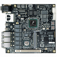
Reference Design Board, Software and Documentation
Termination Type
SMD
Supply Voltage Max
1.05V
Tool / Board Applications
Wired Connectivity-LIN, CAN, Ethernet, USB
Mcu Supported Families
POWERQUICC II PRO
Rohs Compliant
Yes
Filter Terminals
SMD
Silicon Manufacturer
Freescale
Silicon Core Number
MPC83xx
Kit Application Type
Communication & Networking
Application Sub Type
Ethernet
Core Architecture
Power Architecture
Silicon Family Name
PowerQUICC II PRO
For Use With/related Products
MPC8313E
Lead Free Status / RoHS Status
Lead free / RoHS Compliant


Clock Input Timing
4
This section provides the clock input DC and AC electrical characteristics for the MPC8313E.
4.1
Table 7
MPC8313E.
4.2
The primary clock source for the MPC8313E can be one of two inputs, SYS_CLK_IN or PCI_CLK,
depending on whether the device is configured in PCI host or PCI agent mode.
clock input (SYS_CLK_IN/PCI_CLK) AC timing specifications for the MPC8313E.
12
Input high voltage
Input low voltage
SYS_CLK_IN input current
PCI_SYNC_IN input current
PCI_SYNC_IN input current
SYS_CLK_IN/PCI_CLK frequency
SYS_CLK_IN/PCI_CLK cycle time
SYS_CLK_IN/PCI_CLK rise and fall time
SYS_CLK_IN/PCI_CLK duty cycle
SYS_CLK_IN/PCI_CLK jitter
Notes:
1. Caution: The system, core, security block must not exceed their respective maximum or minimum operating frequencies.
2. Rise and fall times for SYS_CLK_IN/PCI_CLK are measured at 0.4 and 2.7 V.
3. Timing is guaranteed by design and characterization.
4. This represents the total input jitter—short term and long term—and is guaranteed by design.
5. The SYS_CLK_IN/PCI_CLK driver’s closed loop jitter bandwidth should be <500 kHz at –20 dB. The bandwidth must be set
low to allow cascade-connected PLL-based devices to track SYS_CLK_IN drivers with the specified jitter.
Clock Input Timing
provides the system clock input (SYS_CLK_IN/PCI_SYNC_IN) DC timing specifications for the
Parameter
DC Electrical Characteristics
AC Electrical Characteristics
Parameter/Condition
MPC8313E PowerQUICC
Table 7. SYS_CLK_IN DC Electrical Characteristics
Table 8. SYS_CLK_IN AC Timing Specifications
NV
0.5 V ≤ V
DD
0 V ≤ V
0 V ≤ V
– 0.5 V ≤ V
Condition
IN
™
≤ NV
—
—
IN
IN
or
II Pro Processor Hardware Specifications, Rev. 3
≤ 0.5 V
≤ NV
t
KHK
DD
IN
f
t
SYS_CLK_IN
SYS_CLK_IN
Symbol
/t
≤ NV
DD
– 0.5 V
t
KH
SYS_CLK_IN
—
, t
DD
KL
Symbol
V
V
I
I
I
IN
IN
IN
IH
Min
IL
0.6
24
15
40
—
Typ
0.8
—
—
—
—
–0.3
Min
2.4
—
—
—
Table 8
66.67
±150
Max
1.2
60
—
Freescale Semiconductor
NV
provides the system
DD
Max
±10
±10
±50
0.4
MHz
Unit
+ 0.3
ns
ns
ps
%
Notes
Unit
4, 5
μA
μA
μA
—
V
V
1
3
2
Related parts for MPC8313E-RDB
Image
Part Number
Description
Manufacturer
Datasheet
Request
R

Part Number:
Description:
Mpc8313e Powerquicc Ii Pro Processor
Manufacturer:
Freescale Semiconductor, Inc
Datasheet:

Part Number:
Description:
BOARD CPU 8313E VER 2.1
Manufacturer:
Freescale Semiconductor
Datasheet:

Part Number:
Description:
BOARD CPU 8313E VER 2.2
Manufacturer:
Freescale Semiconductor
Datasheet:
Part Number:
Description:
Microprocessors - MPU 8313 REV2.2 PB ENC EXT
Manufacturer:
Freescale Semiconductor
Datasheet:
Part Number:
Description:
Microprocessors - MPU 8313 REV2.2 PB W/ENC
Manufacturer:
Freescale Semiconductor
Datasheet:
Part Number:
Description:
Microprocessors - MPU 8313 REV2.2 PB NO EN EXT
Manufacturer:
Freescale Semiconductor
Datasheet:
Part Number:
Description:
Microprocessors - MPU 8313 REV2.2 PB NO ENC
Manufacturer:
Freescale Semiconductor
Datasheet:
Part Number:
Description:
Manufacturer:
Freescale Semiconductor, Inc
Datasheet:
Part Number:
Description:
Manufacturer:
Freescale Semiconductor, Inc
Datasheet:
Part Number:
Description:
Manufacturer:
Freescale Semiconductor, Inc
Datasheet:
Part Number:
Description:
Manufacturer:
Freescale Semiconductor, Inc
Datasheet:
Part Number:
Description:
Manufacturer:
Freescale Semiconductor, Inc
Datasheet:
Part Number:
Description:
Manufacturer:
Freescale Semiconductor, Inc
Datasheet:
Part Number:
Description:
Manufacturer:
Freescale Semiconductor, Inc
Datasheet:
Part Number:
Description:
Manufacturer:
Freescale Semiconductor, Inc
Datasheet: