MPC8313E-RDB Freescale Semiconductor, MPC8313E-RDB Datasheet - Page 34
MPC8313E-RDB
Manufacturer Part Number
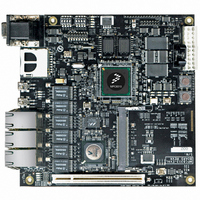
MPC8313E-RDB
Description
BOARD PROCESSOR
Manufacturer
Freescale Semiconductor
Series
PowerQUICC II™ PROr
Type
MCUr
Datasheets
1.MPC8313CZQAFFB.pdf
(100 pages)
2.MPC8313E-RDBB.pdf
(52 pages)
3.MPC8313E-RDBB.pdf
(2 pages)
Specifications of MPC8313E-RDB
Contents
Reference Design Board, Software and Documentation
Termination Type
SMD
Supply Voltage Max
1.05V
Tool / Board Applications
Wired Connectivity-LIN, CAN, Ethernet, USB
Mcu Supported Families
POWERQUICC II PRO
Rohs Compliant
Yes
Filter Terminals
SMD
Silicon Manufacturer
Freescale
Silicon Core Number
MPC83xx
Kit Application Type
Communication & Networking
Application Sub Type
Ethernet
Core Architecture
Power Architecture
Silicon Family Name
PowerQUICC II PRO
For Use With/related Products
MPC8313E
Lead Free Status / RoHS Status
Lead free / RoHS Compliant


Ethernet: Three-Speed Ethernet, MII Management
8.5
The electrical characteristics specified here apply to MII management interface signals MDIO
(management data input/output) and MDC (management data clock). The electrical characteristics for
MII, RMII, RGMII, SGMII, and RTBI are specified in
Controller (eTSEC) (10/100/1000 Mbps)—MII/RMII/RGMII/SGMII/RTBI Electrical Characteristics.”
8.5.1
The MDC and MDIO are defined to operate at a supply voltage of 2.5 V or 3.3 V.
provide the DC electrical characteristics for MDIO and MDC.
34
At recommended operating conditions with L/TV
TSEC_1588_TRIG_IN pulse width
Notes:
1.T
2. It need to be at least two times of clock period of clock selected by TMR_CTRL[CKSEL]. See the MPC8313E PowerQUICC™
3. The maximum value of t
Supply voltage (2.5 V)
Output high voltage
Output low voltage
Input high voltage
Input low voltage
Input high current
Input low current
Note:
1. Note that the symbol V
PowerQUICC™ II Pro Integrated Processor Family Reference Manual, for a description of TMR_CTRL registers.
II Pro Integrated Processor Family Reference Manual, for a description of TMR_CTRL registers.
example, for 10/100/1000 Mbps modes, the maximum value of t
RX_CLK
Parameter/Condition
Parameter
is the max clock period of eTSEC receiving clock selected by TMR_CTRL[CKSEL]. See the MPC8313E
Ethernet Management Interface Electrical Characteristics
MII Management DC Electrical Characteristics
Table 37. MII Management DC Electrical Characteristics When Powered at 2.5 V
MPC8313E PowerQUICC
Table 36. eTSEC IEEE 1588 AC Timing Specifications (continued)
IN
T1588CLK
, in this case, represents the LV
NV
Symbol
DDA
V
V
V
V
I
I
OH
IH
OL
/NV
IL
IH
IL
is not only defined by the value of T
DDB
t
DD
T1588TRIGH
Symbol
I
of 3.3 V ± 5%.
OH
I
OL
™
= –1.0 mA
= 1.0 mA
—
—
II Pro Processor Hardware Specifications, Rev. 3
V
V
IN
IN
1
= NV
= NV
IN
Conditions
2 × t
symbol referenced in
NV
NV
NV
NV
DDA
DDA
—
T1588CLK_MAX
Section 8.1, “Enhanced Three-Speed Ethernet
DDA
DDA
DDA
DDA
T1588CLK
Min
or NV
or NV
or NV
or NV
or NV
or NV
RX_CLK
DDB
DDB
is 3600, 280, and 56 ns, respectively.
DDB
DDB
DDB
DDB
, but also defined by the recovered clock. For
= Min
= Min
= Min
= Min
Typ
Table 1
—
V
and
SS
2.37
2.00
–0.3
Min
–15
1.7
—
Table
– 0.3
Max
—
Table 37
Freescale Semiconductor
2.
NV
NV
DDB
DDA
Unit
Max
2.63
0.40
0.70
10
ns
—
—
and
or
+ 0.3
+ 0.3
Table 38
Notes
2
Unit
μA
μA
V
V
V
V
V
Related parts for MPC8313E-RDB
Image
Part Number
Description
Manufacturer
Datasheet
Request
R

Part Number:
Description:
Mpc8313e Powerquicc Ii Pro Processor
Manufacturer:
Freescale Semiconductor, Inc
Datasheet:

Part Number:
Description:
BOARD CPU 8313E VER 2.1
Manufacturer:
Freescale Semiconductor
Datasheet:

Part Number:
Description:
BOARD CPU 8313E VER 2.2
Manufacturer:
Freescale Semiconductor
Datasheet:
Part Number:
Description:
Microprocessors - MPU 8313 REV2.2 PB ENC EXT
Manufacturer:
Freescale Semiconductor
Datasheet:
Part Number:
Description:
Microprocessors - MPU 8313 REV2.2 PB W/ENC
Manufacturer:
Freescale Semiconductor
Datasheet:
Part Number:
Description:
Microprocessors - MPU 8313 REV2.2 PB NO EN EXT
Manufacturer:
Freescale Semiconductor
Datasheet:
Part Number:
Description:
Microprocessors - MPU 8313 REV2.2 PB NO ENC
Manufacturer:
Freescale Semiconductor
Datasheet:
Part Number:
Description:
Manufacturer:
Freescale Semiconductor, Inc
Datasheet:
Part Number:
Description:
Manufacturer:
Freescale Semiconductor, Inc
Datasheet:
Part Number:
Description:
Manufacturer:
Freescale Semiconductor, Inc
Datasheet:
Part Number:
Description:
Manufacturer:
Freescale Semiconductor, Inc
Datasheet:
Part Number:
Description:
Manufacturer:
Freescale Semiconductor, Inc
Datasheet:
Part Number:
Description:
Manufacturer:
Freescale Semiconductor, Inc
Datasheet:
Part Number:
Description:
Manufacturer:
Freescale Semiconductor, Inc
Datasheet:
Part Number:
Description:
Manufacturer:
Freescale Semiconductor, Inc
Datasheet: