MPC8360E-RDK Freescale Semiconductor, MPC8360E-RDK Datasheet - Page 61
MPC8360E-RDK
Manufacturer Part Number
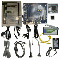
MPC8360E-RDK
Description
BOARD REFERENCE DESIGN FOR MPC
Manufacturer
Freescale Semiconductor
Series
PowerQUICC II™ PROr
Type
MPUr
Specifications of MPC8360E-RDK
Contents
Board, Cables, CD, Power Supply
Processor To Be Evaluated
MPC8360E
Data Bus Width
32 bit
Interface Type
RS-232, Ethernet, USB
Operating Supply Voltage
1.3 V
For Use With/related Products
MPC8360E
Lead Free Status / RoHS Status
Lead free / RoHS Compliant


17.2
Table 58
Figure 44
Figure 45
reference the rising edge of the clock, these AC timing diagrams also apply when the falling edge is the
active edge.
Freescale Semiconductor
Input low voltage
Input current
TDM/SI outputs—External clock delay
TDM/SI outputs—External clock high impedance
TDM/SI inputs—External clock input setup time
TDM/SI inputs—External clock input hold time
Notes:
1. Output specifications are measured from the 50% level of the rising edge of CLKIN to the 50% level of the signal. Timings
2. The symbols used for timing specifications follow the pattern of t
3. Timings are measured from the positive or negative edge of the clock, according to SIxMR [CE] and SITXCEI[TXCEIx]. See
are measured at the pin.
inputs and t
outputs external timing (SE) for the time t
are invalid (X).
the MPC8360E Integrated Communications Processor Family Reference Manual for more details.
MPC8360E/MPC8358E PowerQUICC II Pro Processor Revision 2.x TBGA Silicon Hardware Specifications, Rev. 4
provides the TDM/SI input and output AC timing specifications.
TDM/SI AC Timing Specifications
provides the AC test load for the TDM/SI.
represents the AC timing from
(first two letters of functional block)(reference)(state)(signal)(state)
Characteristic
Output
Characteristic
Table 57. TDM/SI DC Electrical Characteristics (continued)
Table 58. TDM/SI AC Timing Specifications
TDM/SI
Figure 44. TDM/SI AC Test Load
Symbol
Z
Table
0
V
memory clock reference (K) goes from the high state (H) until outputs (O)
I
= 50 Ω
IN
IL
56. Note that although the specifications generally
0 V ≤ V
Condition
(first two letters of functional block)(signal)(state)(reference)(state)
for outputs. For example, t
IN
—
≤ OV
Symbol
t
t
t
t
SEKHOV
SEKHOX
SEIVKH
SEIXKH
R
DD
L
= 50 Ω
2
1
–0.3
Min
—
OV
Min
2
2
5
2
SEKHOX
DD
/2
symbolizes the TDM/SI
Max
±10
Max
0.8
10
10
—
—
3
Unit
Unit
TDM/SI
μA
ns
ns
ns
ns
for
V
61
Related parts for MPC8360E-RDK
Image
Part Number
Description
Manufacturer
Datasheet
Request
R

Part Number:
Description:
Mpc8360e Powerquicc Ii Pro Family
Manufacturer:
Freescale Semiconductor, Inc
Datasheet:

Part Number:
Description:
BOARD PROCESSOR FOR MPC8360E
Manufacturer:
Freescale Semiconductor
Datasheet:
Part Number:
Description:
Manufacturer:
Freescale Semiconductor, Inc
Datasheet:
Part Number:
Description:
Manufacturer:
Freescale Semiconductor, Inc
Datasheet:
Part Number:
Description:
Manufacturer:
Freescale Semiconductor, Inc
Datasheet:
Part Number:
Description:
Manufacturer:
Freescale Semiconductor, Inc
Datasheet:
Part Number:
Description:
Manufacturer:
Freescale Semiconductor, Inc
Datasheet:
Part Number:
Description:
Manufacturer:
Freescale Semiconductor, Inc
Datasheet:
Part Number:
Description:
Manufacturer:
Freescale Semiconductor, Inc
Datasheet:
Part Number:
Description:
Manufacturer:
Freescale Semiconductor, Inc
Datasheet:
Part Number:
Description:
Manufacturer:
Freescale Semiconductor, Inc
Datasheet:
Part Number:
Description:
Manufacturer:
Freescale Semiconductor, Inc
Datasheet:
Part Number:
Description:
Manufacturer:
Freescale Semiconductor, Inc
Datasheet:
Part Number:
Description:
Manufacturer:
Freescale Semiconductor, Inc
Datasheet:
Part Number:
Description:
Manufacturer:
Freescale Semiconductor, Inc
Datasheet: