MPC8360E-RDK Freescale Semiconductor, MPC8360E-RDK Datasheet - Page 92
MPC8360E-RDK
Manufacturer Part Number
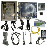
MPC8360E-RDK
Description
BOARD REFERENCE DESIGN FOR MPC
Manufacturer
Freescale Semiconductor
Series
PowerQUICC II™ PROr
Type
MPUr
Specifications of MPC8360E-RDK
Contents
Board, Cables, CD, Power Supply
Processor To Be Evaluated
MPC8360E
Data Bus Width
32 bit
Interface Type
RS-232, Ethernet, USB
Operating Supply Voltage
1.3 V
For Use With/related Products
MPC8360E
Lead Free Status / RoHS Status
Lead free / RoHS Compliant


Clocking
22.3
The QUICC Engine block PLL is controlled by the RCWL[CEPMF], RCWL[CEPDF], and
RCWL[CEVCOD] parameters.
block PLL.
92
MPC8360E/MPC8358E PowerQUICC II Pro Processor Revision 2.x TBGA Silicon Hardware Specifications, Rev. 4
QUICC Engine Block PLL Configuration
Core VCO frequency = Core frequency × VCO divider. The VCO divider
(RCWL[COREPLL[0:1]]) must be set properly so that the core VCO
frequency is in the range of 800–1800 MHz. Having a core frequency below
the CSB frequency is not a possible option because the core frequency must
be equal to or greater than the CSB frequency.
RCWL[CEPMF] RCWL[CEPDF]
0–1
11
00
01
10
11
00
01
10
11
00
01
10
11
Table 74. QUICC Engine Block PLL Multiplication Factors
00000
00001
00010
00011
00100
RCWL[COREPLL]
Table 73. e300 Core PLL Configuration (continued)
Table 74
0001
0010
0010
0010
0010
0010
0010
0010
0010
0011
0011
0011
0011
2–5
shows the multiplication factor encodings for the QUICC Engine
0
0
0
0
0
6
1
0
0
0
0
1
1
1
1
0
0
0
0
NOTE
Multiplication Factor = RCWL[CEPMF]/
core_clk : csb_clk
Ratio
1.5:1
2.5:1
2.5:1
2.5:1
2.5:1
2:1
2:1
2:1
2:1
3:1
3:1
3:1
3:1
(1 + RCWL[CEPDF])
QUICC Engine PLL
Reserved
× 16
× 2
× 3
× 4
VCO divider
÷
÷
÷
÷
÷
÷
÷
÷
÷
÷
÷
÷
÷
8
2
4
8
8
2
4
8
8
2
4
8
8
Freescale Semiconductor
Related parts for MPC8360E-RDK
Image
Part Number
Description
Manufacturer
Datasheet
Request
R

Part Number:
Description:
Mpc8360e Powerquicc Ii Pro Family
Manufacturer:
Freescale Semiconductor, Inc
Datasheet:

Part Number:
Description:
BOARD PROCESSOR FOR MPC8360E
Manufacturer:
Freescale Semiconductor
Datasheet:
Part Number:
Description:
Manufacturer:
Freescale Semiconductor, Inc
Datasheet:
Part Number:
Description:
Manufacturer:
Freescale Semiconductor, Inc
Datasheet:
Part Number:
Description:
Manufacturer:
Freescale Semiconductor, Inc
Datasheet:
Part Number:
Description:
Manufacturer:
Freescale Semiconductor, Inc
Datasheet:
Part Number:
Description:
Manufacturer:
Freescale Semiconductor, Inc
Datasheet:
Part Number:
Description:
Manufacturer:
Freescale Semiconductor, Inc
Datasheet:
Part Number:
Description:
Manufacturer:
Freescale Semiconductor, Inc
Datasheet:
Part Number:
Description:
Manufacturer:
Freescale Semiconductor, Inc
Datasheet:
Part Number:
Description:
Manufacturer:
Freescale Semiconductor, Inc
Datasheet:
Part Number:
Description:
Manufacturer:
Freescale Semiconductor, Inc
Datasheet:
Part Number:
Description:
Manufacturer:
Freescale Semiconductor, Inc
Datasheet:
Part Number:
Description:
Manufacturer:
Freescale Semiconductor, Inc
Datasheet:
Part Number:
Description:
Manufacturer:
Freescale Semiconductor, Inc
Datasheet: