DK-DEV-3CLS200N Altera, DK-DEV-3CLS200N Datasheet - Page 3
DK-DEV-3CLS200N
Manufacturer Part Number
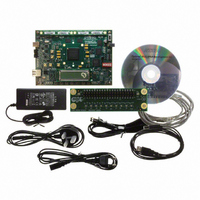
DK-DEV-3CLS200N
Description
KIT DEV CYCLONE III LS EP3CLS200
Manufacturer
Altera
Series
Cyclone® IIIr
Type
FPGAr
Datasheets
1.EP3C5F256C8N.pdf
(34 pages)
2.EP3C5F256C8N.pdf
(14 pages)
3.DK-START-3C25N.pdf
(74 pages)
4.DK-DEV-3CLS200N.pdf
(42 pages)
Specifications of DK-DEV-3CLS200N
Contents
Board
Silicon Manufacturer
Altera
Core Architecture
FPGA
Core Sub-architecture
Cyclone
Silicon Core Number
EP3C
Silicon Family Name
Cyclone III LS
Rohs Compliant
Yes
For Use With/related Products
EP3CLS200
Lead Free Status / RoHS Status
Lead free / RoHS Compliant
Other names
544-2601


Chapter 1: Cyclone III Device Data Sheet
Electrical Characteristics
© January 2010 Altera Corporation
Table 1–2. Cyclone III Devices Maximum Allowed Overshoot During Transitions over a 10-Year Time
Frame
Note to
(1)
Symbol
V
Figure 1–1
voltage is shown in red and is present on the input pin of the Cyclone III device at over 4.1 V but below 4.2 V. From
Table
a 10-year period. Percentage of high time is calculated as ([delta T]/T) × 100. This 10-year period assumes the
device is always turned on with 100% I/O toggle rate and 50% duty cycle signal. For lower I/O toggle rates and
situations in which the device is in an idle state, lifetimes are increased.
i
Table
(Note 1)
1–1, for an overshoot of 4.1 V, the percentage of high time for the overshoot can be as high as 31.97% over
1–2:
Parameter
shows the methodology to determine the overshoot duration. In the example in
AC Input
Voltage
V
V
V
V
V
V
V
V
V
V
V
V
V
Condition
V
I
I
I
I
I
I
I
I
I
I
I
I
I
I
= 3.95 V
= 4.05 V
= 4.10 V
= 4.15 V
= 4.20 V
= 4.25 V
= 4.30 V
= 4.35 V
= 4.40 V
= 4.45 V
= 4.50 V
= 4.60 V
= 4.70 V
= 4.0 V
Overshoot Duration as % of High Time
95.67
55.24
31.97
18.52
10.74
0.047
Cyclone III Device Handbook, Volume 2
6.23
3.62
1.22
0.71
0.41
0.14
100
2.1
Figure
1–1, overshoot
Unit
%
%
%
%
%
%
%
%
%
%
%
%
%
%
1–3
Related parts for DK-DEV-3CLS200N
Image
Part Number
Description
Manufacturer
Datasheet
Request
R

Part Number:
Description:
KIT DEV ARRIA II GX FPGA 2AGX125
Manufacturer:
Altera
Datasheet:

Part Number:
Description:
KIT DEV STRATIX IV FPGA 4SE530
Manufacturer:
Altera
Datasheet:

Part Number:
Description:
KIT DEV FPGA 2AGX260 W/6.375G TX
Manufacturer:
Altera
Datasheet:

Part Number:
Description:
KIT DEV MAX V 5M570Z
Manufacturer:
Altera
Datasheet:

Part Number:
Description:
KIT DEV STRATIX V FPGA 5SGXEA7
Manufacturer:
Altera
Datasheet:

Part Number:
Description:
KIT DEVELOPMENT STRATIX III
Manufacturer:
Altera
Datasheet:

Part Number:
Description:
KIT DEVELOPMENT STRATIX IV
Manufacturer:
Altera
Datasheet:

Part Number:
Description:
KIT DEV ARRIA GX 1AGX60N
Manufacturer:
Altera
Datasheet:
Part Number:
Description:
KIT STARTER CYCLONE IV GX
Manufacturer:
Altera
Datasheet:
Part Number:
Description:
KIT DEVELOPMENT STRATIX IV
Manufacturer:
Altera
Datasheet:

Part Number:
Description:
CPLD, EP610 Family, ECMOS Process, 300 Gates, 16 Macro Cells, 16 Reg., 16 User I/Os, 5V Supply, 35 Speed Grade, 24DIP
Manufacturer:
Altera Corporation
Datasheet:
Part Number:
Description:
CPLD, EP610 Family, ECMOS Process, 300 Gates, 16 Macro Cells, 16 Reg., 16 User I/Os, 5V Supply, 15 Speed Grade, 24DIP
Manufacturer:
Altera Corporation
Datasheet: