DK-DEV-3CLS200N Altera, DK-DEV-3CLS200N Datasheet - Page 4
DK-DEV-3CLS200N
Manufacturer Part Number
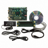
DK-DEV-3CLS200N
Description
KIT DEV CYCLONE III LS EP3CLS200
Manufacturer
Altera
Series
Cyclone® IIIr
Type
FPGAr
Datasheets
1.EP3C5F256C8N.pdf
(34 pages)
2.EP3C5F256C8N.pdf
(14 pages)
3.DK-START-3C25N.pdf
(74 pages)
4.DK-DEV-3CLS200N.pdf
(42 pages)
Specifications of DK-DEV-3CLS200N
Contents
Board
Silicon Manufacturer
Altera
Core Architecture
FPGA
Core Sub-architecture
Cyclone
Silicon Core Number
EP3C
Silicon Family Name
Cyclone III LS
Rohs Compliant
Yes
For Use With/related Products
EP3CLS200
Lead Free Status / RoHS Status
Lead free / RoHS Compliant
Other names
544-2601


1–4
Table 1–3. Cyclone III Devices Recommended Operating Conditions
Cyclone III Device Handbook, Volume 2
V
V
V
V
V
V
C CINT
C CIO
C CA
C CD_P LL
I
O
Symbol
(3)
(3),
(3)
(3)
(4)
Supply voltage for internal logic
Supply voltage for output buffers, 3.3-V
operation
Supply voltage for output buffers, 3.0-V
operation
Supply voltage for output buffers, 2.5-V
operation
Supply voltage for output buffers, 1.8-V
operation
Supply voltage for output buffers, 1.5-V
operation
Supply voltage for output buffers, 1.2-V
operation
Supply (analog) voltage for PLL
regulator
Supply (digital) voltage for PLL
Input voltage
Output voltage
Figure 1–1
Figure 1–1. Cyclone III Devices Overshoot Duration
Recommended Operating Conditions
This section lists the functional operation limits for AC and DC parameters for
Cyclone III devices. The steady-state voltage and current values expected from
Cyclone III devices are provided in
without plateaus.
Parameter
shows the methodology to determine the overshoot duration.
4.2 V
4.1 V
3.3 V
ΔT
Table
Conditions
(Note 1)
—
—
—
—
—
—
—
—
—
—
—
1–3. All supplies must be strictly monotonic
T
,
(2)
(Part 1 of 2)
Chapter 1: Cyclone III Device Data Sheet
3.135
2.375
1.425
2.375
1.15
2.85
1.71
1.14
1.15
–0.5
Min
0
© January 2010 Altera Corporation
Typ
1.2
3.3
2.5
1.8
1.5
1.2
2.5
1.2
—
—
3
Electrical Characteristics
3.465
2.625
1.575
2.625
Max
1.25
3.15
1.89
1.26
1.25
V
3.6
CC IO
Unit
V
V
V
V
V
V
V
V
V
V
V
Related parts for DK-DEV-3CLS200N
Image
Part Number
Description
Manufacturer
Datasheet
Request
R

Part Number:
Description:
KIT DEV ARRIA II GX FPGA 2AGX125
Manufacturer:
Altera
Datasheet:

Part Number:
Description:
KIT DEV STRATIX IV FPGA 4SE530
Manufacturer:
Altera
Datasheet:

Part Number:
Description:
KIT DEV FPGA 2AGX260 W/6.375G TX
Manufacturer:
Altera
Datasheet:

Part Number:
Description:
KIT DEV MAX V 5M570Z
Manufacturer:
Altera
Datasheet:

Part Number:
Description:
KIT DEV STRATIX V FPGA 5SGXEA7
Manufacturer:
Altera
Datasheet:

Part Number:
Description:
KIT DEVELOPMENT STRATIX III
Manufacturer:
Altera
Datasheet:

Part Number:
Description:
KIT DEVELOPMENT STRATIX IV
Manufacturer:
Altera
Datasheet:

Part Number:
Description:
KIT DEV ARRIA GX 1AGX60N
Manufacturer:
Altera
Datasheet:
Part Number:
Description:
KIT STARTER CYCLONE IV GX
Manufacturer:
Altera
Datasheet:
Part Number:
Description:
KIT DEVELOPMENT STRATIX IV
Manufacturer:
Altera
Datasheet:

Part Number:
Description:
CPLD, EP610 Family, ECMOS Process, 300 Gates, 16 Macro Cells, 16 Reg., 16 User I/Os, 5V Supply, 35 Speed Grade, 24DIP
Manufacturer:
Altera Corporation
Datasheet:
Part Number:
Description:
CPLD, EP610 Family, ECMOS Process, 300 Gates, 16 Macro Cells, 16 Reg., 16 User I/Os, 5V Supply, 15 Speed Grade, 24DIP
Manufacturer:
Altera Corporation
Datasheet: