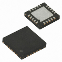
ATTINY25V-10MU Atmel, ATTINY25V-10MU Datasheet - Page 109

ATTINY25V-10MU
Manufacturer Part Number
ATTINY25V-10MU
Description
IC MCU AVR 2K FLASH 10MHZ 20-QFN
Manufacturer
Atmel
Series
AVR® ATtinyr
Specifications of ATTINY25V-10MU
Core Processor
AVR
Core Size
8-Bit
Speed
10MHz
Connectivity
USI
Peripherals
Brown-out Detect/Reset, POR, PWM, WDT
Number Of I /o
6
Program Memory Size
2KB (1K x 16)
Program Memory Type
FLASH
Eeprom Size
128 x 8
Ram Size
128 x 8
Voltage - Supply (vcc/vdd)
1.8 V ~ 5.5 V
Data Converters
A/D 4x10b
Oscillator Type
Internal
Operating Temperature
-40°C ~ 85°C
Package / Case
20-MLF®, QFN
Processor Series
ATTINY2x
Core
AVR8
Data Bus Width
8 bit
Data Ram Size
128 B
Interface Type
USI
Maximum Clock Frequency
10 MHz
Number Of Programmable I/os
6
Number Of Timers
2
Operating Supply Voltage
1.8 V to 5.5 V
Maximum Operating Temperature
+ 85 C
Mounting Style
SMD/SMT
Minimum Operating Temperature
- 40 C
On-chip Adc
4-ch x 10-bit
For Use With
ATSTK600-DIP40 - STK600 SOCKET/ADAPTER 40-PDIPATAVRBC100 - REF DESIGN KIT BATTERY CHARGER770-1007 - ISP 4PORT ATMEL AVR MCU SPI/JTAGATAVRDRAGON - KIT DRAGON 32KB FLASH MEM AVRATAVRISP2 - PROGRAMMER AVR IN SYSTEMATJTAGICE2 - AVR ON-CHIP D-BUG SYSTEM
Lead Free Status / RoHS Status
Lead free / RoHS Compliant
Available stocks
Company
Part Number
Manufacturer
Quantity
Price
Company:
Part Number:
ATTINY25V-10MU
Manufacturer:
ATMEL
Quantity:
1 650
Part Number:
ATTINY25V-10MU
Manufacturer:
ATMEL/爱特梅尔
Quantity:
20 000
- Current page: 109 of 236
- Download datasheet (5Mb)
14.1
14.1.1
2586M–AVR–07/10
Register Description
DTPS1 – Timer/Counter1 Dead Time Prescaler Register 1
The length of the counting period is user adjustable by selecting the dead time prescaler setting
in 0x23 register, and selecting then the dead time value in I/O register DT1x. The DT1x register
consists of two 4-bit fields, DT1xH and DT1xL that control the dead time periods of the PWM
output and its’ complementary output separately. Thus the rising edge of OC1x and OC1x can
have different dead time periods. The dead time is adjusted as the number of prescaled dead
time generator clock cycles.
Figure 14-3. The Complementary Output Pair
The dead time prescaler register, DTPS1 is a 2-bit read/write register.
• Bits 1:0 – DTPS1[1:0]: Dead Time Prescaler
The dedicated Dead Time prescaler in front of the Dead Time Generator can divide the
Timer/Counter1 clock (PCK or CK) by 1, 2, 4 or 8 providing a large range of dead times that can
be generated. The Dead Time prescaler is controlled by two bits DTPS1[1:0] from the Dead
Time Prescaler register. These bits define the division factor of the Dead Time prescaler. The
division factors are given in table 46.
Table 14-1.
Bit
0x23
Read/Write
Initial value
DTPS11
PWM1x
OC1x
OC1x
x = A or B
0
0
1
1
t
non-overlap / rising edge
Division factors of the Dead Time prescaler
R
7
0
DTPS10
0
1
0
1
R
6
0
Prescaler divides the T/C1 clock by
1x (no division)
2x
4x
8x
t
non-overlap / falling edge
R
5
0
R
4
0
R
3
0
R
2
0
DTPS11
R/W
1
0
DTPS10
R/W
0
0
DTPS1
109
Related parts for ATTINY25V-10MU
Image
Part Number
Description
Manufacturer
Datasheet
Request
R

Part Number:
Description:
MCU AVR 2K FLASH 4MHZ 8-SOIC
Manufacturer:
Atmel
Datasheet:

Part Number:
Description:
MCU AVR 2KB FLASH 10MHZ 8SOIC
Manufacturer:
Atmel
Datasheet:

Part Number:
Description:
IC AVR MCU 2K 10MHZ 8-DIP
Manufacturer:
Atmel
Datasheet:

Part Number:
Description:
IC MCU AVR 2KB FLASH 10MHZ 8SOIC
Manufacturer:
Atmel
Datasheet:

Part Number:
Description:
IC MCU AVR 2KB FLASH 10MHZ 8SOIC
Manufacturer:
Atmel
Datasheet:

Part Number:
Description:
MCU AVR 2KB FLASH 10MHZ 8SOIC
Manufacturer:
Atmel
Datasheet:

Part Number:
Description:
MCU AVR 2KB FLASH 10MHZ 20QFN
Manufacturer:
Atmel
Datasheet:

Part Number:
Description:
MCU AVR 2K ISP FLASH 1.8V 8-SOIC
Manufacturer:
Atmel
Datasheet:

Part Number:
Description:
IC AVR MCU 2K 10MHZ 8DIP
Manufacturer:
Atmel
Datasheet:

Part Number:
Description:
IC AVR MCU 2K 10MHZ 8SOIC
Manufacturer:
Atmel
Datasheet:

Part Number:
Description:
8-bit Microcontrollers - MCU 2KB FLASH,128B EE, 128B SRAM-10MHz
Manufacturer:
Atmel

Part Number:
Description:
8-bit Microcontrollers - MCU 2KB FL,128B EE,128B SRAM-10MHz
Manufacturer:
Atmel

Part Number:
Description:
8-bit Microcontrollers - MCU AVR 16KB FL 512B EE 1KB SRAM 10 MHZ GRN
Manufacturer:
Atmel


