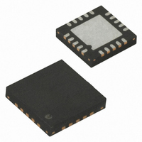
ATTINY25V-10MU Atmel, ATTINY25V-10MU Datasheet - Page 117

ATTINY25V-10MU
Manufacturer Part Number
ATTINY25V-10MU
Description
IC MCU AVR 2K FLASH 10MHZ 20-QFN
Manufacturer
Atmel
Series
AVR® ATtinyr
Specifications of ATTINY25V-10MU
Core Processor
AVR
Core Size
8-Bit
Speed
10MHz
Connectivity
USI
Peripherals
Brown-out Detect/Reset, POR, PWM, WDT
Number Of I /o
6
Program Memory Size
2KB (1K x 16)
Program Memory Type
FLASH
Eeprom Size
128 x 8
Ram Size
128 x 8
Voltage - Supply (vcc/vdd)
1.8 V ~ 5.5 V
Data Converters
A/D 4x10b
Oscillator Type
Internal
Operating Temperature
-40°C ~ 85°C
Package / Case
20-MLF®, QFN
Processor Series
ATTINY2x
Core
AVR8
Data Bus Width
8 bit
Data Ram Size
128 B
Interface Type
USI
Maximum Clock Frequency
10 MHz
Number Of Programmable I/os
6
Number Of Timers
2
Operating Supply Voltage
1.8 V to 5.5 V
Maximum Operating Temperature
+ 85 C
Mounting Style
SMD/SMT
Minimum Operating Temperature
- 40 C
On-chip Adc
4-ch x 10-bit
For Use With
ATSTK600-DIP40 - STK600 SOCKET/ADAPTER 40-PDIPATAVRBC100 - REF DESIGN KIT BATTERY CHARGER770-1007 - ISP 4PORT ATMEL AVR MCU SPI/JTAGATAVRDRAGON - KIT DRAGON 32KB FLASH MEM AVRATAVRISP2 - PROGRAMMER AVR IN SYSTEMATJTAGICE2 - AVR ON-CHIP D-BUG SYSTEM
Lead Free Status / RoHS Status
Lead free / RoHS Compliant
Available stocks
Company
Part Number
Manufacturer
Quantity
Price
Company:
Part Number:
ATTINY25V-10MU
Manufacturer:
ATMEL
Quantity:
1 650
Part Number:
ATTINY25V-10MU
Manufacturer:
ATMEL/爱特梅尔
Quantity:
20 000
- Current page: 117 of 236
- Download datasheet (5Mb)
15.3.5
15.3.6
15.4
15.4.1
15.4.2
15.4.3
2586M–AVR–07/10
Alternative USI Usage
Start Condition Detector
Clock speed considerations
Half-Duplex Asynchronous Data Transfer
4-Bit Counter
12-Bit Timer/Counter
If the slave is not able to receive more data it does not acknowledge the data byte it has last
received. When the master does a read operation it must terminate the operation by forcing the
acknowledge bit low after the last byte transmitted.
The start condition detector is shown in
to 300 ns) to ensure valid sampling of the SCL line. The start condition detector is only enabled
in two-wire mode.
Figure 15-6. Start Condition Detector, Logic Diagram
The start condition detector is working asynchronously and can therefore wake up the processor
from power-down sleep mode. However, the protocol used might have restrictions on the SCL
hold time. Therefore, when using this feature the oscillator start-up time (set by CKSEL fuses,
see
Refer to the description of the USISIF bit on
Maximum frequency for SCL and SCK is f
receive rate in both two- and three-wire mode. In two-wire slave mode the Two-wire Clock Con-
trol Unit will hold the SCL low until the slave is ready to receive more data. This may reduce the
actual data rate in two-wire mode.
The flexible design of the USI allows it to be used for other tasks when serial communication is
not needed. Below are some examples.
Using the USI Data Register in three-wire mode it is possible to implement a more compact and
higher performance UART than by software, only.
The 4-bit counter can be used as a stand-alone counter with overflow interrupt. Note that if the
counter is clocked externally, both clock edges will increment the counter value.
Combining the 4-bit USI counter with one of the 8-bit timer/counters creates a 12-bit counter.
6. Multiple bytes can now be transmitted, all in same direction, until a stop condition is
“Clock Systems and their Distribution” on page
enables its output. If the bit is set, a master read operation is in progress (i.e., the slave
drives the SDA line) The slave can hold the SCL line low after the acknowledge (E).
given by the master (F), or a new start condition is given.
Write( USISIF)
SDA
SCL
Figure
CK
page 119
/ 2. This is also the maximum data transmit and
15-6. The SDA line is delayed (in the range of 50
23) must also be taken into consideration.
D Q
CLR
for further details.
D Q
CLR
USISIF
CLOCK
HOLD
117
Related parts for ATTINY25V-10MU
Image
Part Number
Description
Manufacturer
Datasheet
Request
R

Part Number:
Description:
MCU AVR 2K FLASH 4MHZ 8-SOIC
Manufacturer:
Atmel
Datasheet:

Part Number:
Description:
MCU AVR 2KB FLASH 10MHZ 8SOIC
Manufacturer:
Atmel
Datasheet:

Part Number:
Description:
IC AVR MCU 2K 10MHZ 8-DIP
Manufacturer:
Atmel
Datasheet:

Part Number:
Description:
IC MCU AVR 2KB FLASH 10MHZ 8SOIC
Manufacturer:
Atmel
Datasheet:

Part Number:
Description:
IC MCU AVR 2KB FLASH 10MHZ 8SOIC
Manufacturer:
Atmel
Datasheet:

Part Number:
Description:
MCU AVR 2KB FLASH 10MHZ 8SOIC
Manufacturer:
Atmel
Datasheet:

Part Number:
Description:
MCU AVR 2KB FLASH 10MHZ 20QFN
Manufacturer:
Atmel
Datasheet:

Part Number:
Description:
MCU AVR 2K ISP FLASH 1.8V 8-SOIC
Manufacturer:
Atmel
Datasheet:

Part Number:
Description:
IC AVR MCU 2K 10MHZ 8DIP
Manufacturer:
Atmel
Datasheet:

Part Number:
Description:
IC AVR MCU 2K 10MHZ 8SOIC
Manufacturer:
Atmel
Datasheet:

Part Number:
Description:
8-bit Microcontrollers - MCU 2KB FLASH,128B EE, 128B SRAM-10MHz
Manufacturer:
Atmel

Part Number:
Description:
8-bit Microcontrollers - MCU 2KB FL,128B EE,128B SRAM-10MHz
Manufacturer:
Atmel

Part Number:
Description:
8-bit Microcontrollers - MCU AVR 16KB FL 512B EE 1KB SRAM 10 MHZ GRN
Manufacturer:
Atmel


