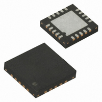
ATTINY25V-10MU Atmel, ATTINY25V-10MU Datasheet - Page 29

ATTINY25V-10MU
Manufacturer Part Number
ATTINY25V-10MU
Description
IC MCU AVR 2K FLASH 10MHZ 20-QFN
Manufacturer
Atmel
Series
AVR® ATtinyr
Specifications of ATTINY25V-10MU
Core Processor
AVR
Core Size
8-Bit
Speed
10MHz
Connectivity
USI
Peripherals
Brown-out Detect/Reset, POR, PWM, WDT
Number Of I /o
6
Program Memory Size
2KB (1K x 16)
Program Memory Type
FLASH
Eeprom Size
128 x 8
Ram Size
128 x 8
Voltage - Supply (vcc/vdd)
1.8 V ~ 5.5 V
Data Converters
A/D 4x10b
Oscillator Type
Internal
Operating Temperature
-40°C ~ 85°C
Package / Case
20-MLF®, QFN
Processor Series
ATTINY2x
Core
AVR8
Data Bus Width
8 bit
Data Ram Size
128 B
Interface Type
USI
Maximum Clock Frequency
10 MHz
Number Of Programmable I/os
6
Number Of Timers
2
Operating Supply Voltage
1.8 V to 5.5 V
Maximum Operating Temperature
+ 85 C
Mounting Style
SMD/SMT
Minimum Operating Temperature
- 40 C
On-chip Adc
4-ch x 10-bit
For Use With
ATSTK600-DIP40 - STK600 SOCKET/ADAPTER 40-PDIPATAVRBC100 - REF DESIGN KIT BATTERY CHARGER770-1007 - ISP 4PORT ATMEL AVR MCU SPI/JTAGATAVRDRAGON - KIT DRAGON 32KB FLASH MEM AVRATAVRISP2 - PROGRAMMER AVR IN SYSTEMATJTAGICE2 - AVR ON-CHIP D-BUG SYSTEM
Lead Free Status / RoHS Status
Lead free / RoHS Compliant
Available stocks
Company
Part Number
Manufacturer
Quantity
Price
Company:
Part Number:
ATTINY25V-10MU
Manufacturer:
ATMEL
Quantity:
1 650
Part Number:
ATTINY25V-10MU
Manufacturer:
ATMEL/爱特梅尔
Quantity:
20 000
- Current page: 29 of 236
- Download datasheet (5Mb)
6.2.4
6.2.5
2586M–AVR–07/10
Internal 128 kHz Oscillator
Low-Frequency Crystal Oscillator
The 128 kHz internal Oscillator is a low power Oscillator providing a clock of 128 kHz. The fre-
quency is nominal at 3V and 25°C. This clock may be select as the system clock by
programming the CKSEL Fuses to “0100”.
When this clock source is selected, start-up times are determined by the SUT Fuses as shown in
Table
Table 6-9.
Note:
To use a 32.768 kHz watch crystal as the clock source for the device, the Low-frequency Crystal
Oscillator must be selected by setting CKSEL fuses to ‘0110’. The crystal should be connected
as shown in
the manufacturer’s datasheet.
When this oscillator is selected, start-up times are determined by the SUT fuses as shown in
Table
Table 6-10.
Note:
The Low-frequency Crystal Oscillator provides an internal load capacitance, see
each TOSC pin.
Table 6-11.
SUT[1:0]
SUT[1:0]
00
01
10
11
00
01
10
11
ATtiny25/45/85
6-9.
6-10.
1. If the RSTDISBL fuse is programmed, this start-up time will be increased to 14CK + 4 ms to
1. These options should be used only if frequency stability at start-up is not important.
Device
ensure programming mode can be entered.
Figure
Start-up Time from
Start-up Times for the 128 kHz Internal Oscillator
Start-up Times for the Low Frequency Crystal Oscillator Clock Selection
Capacitance of Low-Frequency Crystal Oscillator
32K (32768) CK
1K (1024) CK
1K (1024) CK
Power Down
Start-up Time from
6-5. To find suitable load capacitance for a 32.768 kHz crysal, please consult
Power-down
6 CK
6 CK
6 CK
(1)
(1)
32 kHz Osc. Type
System Osc.
Additional Delay from
Reset (V
64 ms
64 ms
4 ms
Additional Delay from
CC
= 5.0V)
Reserved
Reserved
14CK + 64 ms
14CK + 4 ms
14CK
Reset
Cap (Xtal1/Tosc1)
(1)
Recommended usage
Fast rising power or BOD enabled
Slowly rising power
Stable frequency at start-up
16 pF
BOD enabled
Fast rising power
Slowly rising power
Recommended Usage
Cap (Xtal2/Tosc2)
Table 6-11
6 pF
29
at
Related parts for ATTINY25V-10MU
Image
Part Number
Description
Manufacturer
Datasheet
Request
R

Part Number:
Description:
MCU AVR 2K FLASH 4MHZ 8-SOIC
Manufacturer:
Atmel
Datasheet:

Part Number:
Description:
MCU AVR 2KB FLASH 10MHZ 8SOIC
Manufacturer:
Atmel
Datasheet:

Part Number:
Description:
IC AVR MCU 2K 10MHZ 8-DIP
Manufacturer:
Atmel
Datasheet:

Part Number:
Description:
IC MCU AVR 2KB FLASH 10MHZ 8SOIC
Manufacturer:
Atmel
Datasheet:

Part Number:
Description:
IC MCU AVR 2KB FLASH 10MHZ 8SOIC
Manufacturer:
Atmel
Datasheet:

Part Number:
Description:
MCU AVR 2KB FLASH 10MHZ 8SOIC
Manufacturer:
Atmel
Datasheet:

Part Number:
Description:
MCU AVR 2KB FLASH 10MHZ 20QFN
Manufacturer:
Atmel
Datasheet:

Part Number:
Description:
MCU AVR 2K ISP FLASH 1.8V 8-SOIC
Manufacturer:
Atmel
Datasheet:

Part Number:
Description:
IC AVR MCU 2K 10MHZ 8DIP
Manufacturer:
Atmel
Datasheet:

Part Number:
Description:
IC AVR MCU 2K 10MHZ 8SOIC
Manufacturer:
Atmel
Datasheet:

Part Number:
Description:
8-bit Microcontrollers - MCU 2KB FLASH,128B EE, 128B SRAM-10MHz
Manufacturer:
Atmel

Part Number:
Description:
8-bit Microcontrollers - MCU 2KB FL,128B EE,128B SRAM-10MHz
Manufacturer:
Atmel

Part Number:
Description:
8-bit Microcontrollers - MCU AVR 16KB FL 512B EE 1KB SRAM 10 MHZ GRN
Manufacturer:
Atmel


