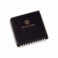
PIC16LC65-04I/L Microchip Technology, PIC16LC65-04I/L Datasheet - Page 325

PIC16LC65-04I/L
Manufacturer Part Number
PIC16LC65-04I/L
Description
IC MIC CTL 4K LP OTP IT 44PLCC
Manufacturer
Microchip Technology
Series
PIC® 16Cr
Datasheet
1.PIC16LC62A-04SP.pdf
(337 pages)
Specifications of PIC16LC65-04I/L
Core Processor
PIC
Core Size
8-Bit
Speed
4MHz
Connectivity
I²C, SPI, UART/USART
Peripherals
POR, PWM, WDT
Number Of I /o
33
Program Memory Size
7KB (4K x 14)
Program Memory Type
OTP
Ram Size
192 x 8
Voltage - Supply (vcc/vdd)
3 V ~ 6 V
Oscillator Type
External
Operating Temperature
-40°C ~ 85°C
Package / Case
44-PLCC
Lead Free Status / RoHS Status
Request inventory verification / Request inventory verification
Eeprom Size
-
Data Converters
-
- Current page: 325 of 337
- Download datasheet (3Mb)
TMR0 .................................................... 24, 26, 28, 30, 32, 34
TMR0 Clock Source Select bit, T0CS................................. 36
TMR0 Interrupt.................................................................... 65
TMR0 Overflow Interrupt Enable bit, T0IE .......................... 37
TMR0 Overflow Interrupt Flag bit, T0IF .............................. 37
TMR0 Prescale Selection Table ......................................... 36
TMR0 Source Edge Select bit, T0SE.................................. 36
TMR1 Overflow Interrupt Enable bit, TMR1IE .................... 38
TMR1 Overflow Interrupt Flag bit, TMR1IF ......................... 41
TMR1CS ............................................................................. 71
TMR1H.................................................. 24, 26, 28, 30, 32, 34
TMR1IE............................................................................... 38
TMR1IF ............................................................................... 41
TMR1L .................................................. 24, 26, 28, 30, 32, 34
TMR1ON............................................................................. 71
TMR2 .................................................... 24, 26, 28, 30, 32, 34
TMR2 Register.................................................................... 75
TMR2 to PR2 Match Interrupt Enable bit, TMR2IE............. 38
TMR2 to PR2 Match Interrupt Flag bit, TMR2IF ................. 41
TMR2IE............................................................................... 38
TMR2IF ............................................................................... 41
TMR2ON............................................................................. 75
TO ............................................................................... 35, 131
TOUTPS3:TOUTPS0.......................................................... 75
Transmit Enable bit, TXEN ............................................... 105
Transmit Shift Register Status bit, TRMT ......................... 105
Transmit Status and Control Register............................... 105
TRISA ............................................. 25, 27, 29, 31, 33, 34, 51
TRISB ............................................. 25, 27, 29, 31, 33, 34, 53
TRISC ....................................... 25, 27, 29, 31, 33, 34, 55, 94
TRISD ............................................. 25, 27, 29, 31, 33, 34, 57
TRISE ............................................. 25, 27, 29, 31, 33, 34, 58
TRMT ................................................................................ 105
TX9 ................................................................................... 105
TX9D................................................................................. 105
TXEN ................................................................................ 105
TXIE .................................................................................... 39
TXIF .................................................................................... 42
TXREG.................................................. 24, 26, 28, 30, 32, 34
TXSTA .......................................... 25, 27, 29, 31, 33, 34, 105
U
UA ................................................................................. 84, 89
Universal Synchronous Asynchronous Receiver Transmitter
(USART)
1997 Microchip Technology Inc.
Asynchronous Mode
Asynchronous Receiver
Asynchronous Receiver Mode
Section ...................................................................... 105
Synchronous Master Mode
Setting Up Transmission................................... 113
Timing Diagram, Master Transmission ............. 113
Transmitter........................................................ 112
Setting Up Reception........................................ 115
Timing Diagram ................................................ 114
Block Diagram .................................................. 114
Section.............................................................. 114
Reception.......................................................... 118
Section.............................................................. 116
Setting Up Reception........................................ 118
Setting Up Transmission................................... 116
Timing Diagram, Reception .............................. 119
Timing Diagram, Transmission ......................... 117
Transmission .................................................... 116
Update Address bit, UA .................................................84, 89
USART Receive Interrupt Enable bit, RCIE ........................39
USART Receive Interrupt Flag bit, RCIF.............................42
USART Transmit Interrupt Enable bit, TXIE ........................39
USART Transmit Interrupt Flag bit, TXIF ............................42
UV Erasable Devices.............................................................7
W
Wake-up from Sleep..........................................................141
Wake-up on Key Depression...............................................53
Wake-up Using Interrupts..................................................141
Watchdog Timer (WDT)
WCOL............................................................................85, 90
Weak Internal Pull-ups ........................................................53
Write Collision Detect bit, WCOL...................................85, 90
X
XMIT_MODE .....................................................................104
XT ......................................................................................130
Z
Z ..........................................................................................35
Zero bit ............................................................................9, 35
Synchronous Slave Mode
Transmit Block Diagram ............................................112
Block Diagram ...........................................................140
Period ........................................................................140
Programming Considerations ....................................140
Section.......................................................................140
Reception ..........................................................120
Section ..............................................................120
Setting Up Reception ........................................120
Setting Up Transmission ...................................120
Transmit ............................................................120
PIC16C6X
DS30234D-page 325
Related parts for PIC16LC65-04I/L
Image
Part Number
Description
Manufacturer
Datasheet
Request
R

Part Number:
Description:
IC MIC CTL 4K LP OTP IT 40DIP
Manufacturer:
Microchip Technology
Datasheet:

Part Number:
Description:
Manufacturer:
Microchip Technology Inc.
Datasheet:

Part Number:
Description:
Manufacturer:
Microchip Technology Inc.
Datasheet:

Part Number:
Description:
Manufacturer:
Microchip Technology Inc.
Datasheet:

Part Number:
Description:
Manufacturer:
Microchip Technology Inc.
Datasheet:

Part Number:
Description:
Manufacturer:
Microchip Technology Inc.
Datasheet:

Part Number:
Description:
Manufacturer:
Microchip Technology Inc.
Datasheet:

Part Number:
Description:
Manufacturer:
Microchip Technology Inc.
Datasheet:

Part Number:
Description:
Manufacturer:
Microchip Technology Inc.
Datasheet:


