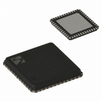
XE1203FI063TRLF Semtech, XE1203FI063TRLF Datasheet - Page 12

XE1203FI063TRLF
Manufacturer Part Number
XE1203FI063TRLF
Description
IC TXRX 433/868/915MHZ 48-VQFN
Manufacturer
Semtech
Specifications of XE1203FI063TRLF
Frequency
180MHz Center
Data Rate - Maximum
152.3kbps
Modulation Or Protocol
FSK
Applications
AMR, ISM, Home Automation, Process Control
Power - Output
0 ~ 15dBm
Sensitivity
-114dBm
Voltage - Supply
2.4 V ~ 3.6 V
Current - Receiving
14mA
Current - Transmitting
62mA
Data Interface
PCB, Surface Mount
Antenna Connector
PCB, Surface Mount
Operating Temperature
-40°C ~ 85°C
Package / Case
48-VQFN
Receiving Current
14mA
Transmitting Current
62mA
Data Rate
152.3Kbps
Modulation Type
FSK
No. Of Pins
48
Supply Voltage Range
2.4V To 3.6V
Operating Temperature Range
-40°C To +85°C
Operating Temperature (min)
-40C
Operating Temperature (max)
85C
Operating Temperature Classification
Industrial
Product Depth (mm)
7mm
Product Length (mm)
7mm
Operating Supply Voltage (typ)
2.5/3.3V
Operating Supply Voltage (max)
3.6V
Lead Free Status / RoHS Status
Lead free / RoHS Compliant
Memory Size
-
Lead Free Status / Rohs Status
Compliant
Other names
XE1203FI063TR
Available stocks
Company
Part Number
Manufacturer
Quantity
Price
Company:
Part Number:
XE1203FI063TRLF
Manufacturer:
SEMTECH
Quantity:
1 100
Company:
Part Number:
XE1203FI063TRLF
Manufacturer:
Semtech
Quantity:
2 300
Part Number:
XE1203FI063TRLF
Manufacturer:
SEMTECH/美国升特
Quantity:
20 000
4.1.8
When enabled this function provides an indication of the frequency error of the local oscillator compared with the
received carrier frequency. For guaranteed operation of the FEI function the following two conditions should be
met:
1) The modulation index, β, should meet the following condition:
where: Δf = frequency deviation of the modulated input signal, BR = input data bit-rate.
2) The bandwidth of the baseband filter (BBW) must be greater than the sum of the frequency offset and the
received peak signal bandwidth, as defined below:
BBW > f
where BBW is the baseband filter bandwidth defined by the RTParam_BW register. f
between the carrier frequency and the LO frequency, and BW
Note on the timing for FEI measurement: The timing diagram of the FEI measurement process is illustrated in
Figure 7 below. As long as the FEI function remains enabled, the frequency error is continuously measured every
2/BR seconds, starting TS_FEI (see Paragraph 3.2.2) after the FEI function is enabled. The measurement results
are loaded into the status registers Dataout_MSB_fei and Dataout_LSB_fei each time the Dataout_LSB_fei
register is read through the 3-wire serial interface. In the diagram below, Saout_fei is generated internally during a
read sequence from the “Dataout_LSB_fei ‘’ status register.
The maximum frequency of SCK during the FEI read operation is 100 kHz. When using the Konnex standard, the
bit ADParam_enable_konnex Configuration Register must be set to ‘1’.
© Semtech 2008
β
=
Dataout_MSB_fei&
2
BR
Dataout_LSB_fei
Δ ⋅
RTParam_FEI
Frequency Error Indicator – FEI
OFFSET
f
≥
saout_fei
, 2
EN
fei_out
+ BW
SIGNAL
Figure 7: Timing diagram of the FEI measurement process
first
evaluation
xxx
TS_FEI
val0
12
SIGNAL
val1
is equal to
val1
2/BR
val2
⎛
⎜
⎝
BR
2
+ f
Δ
⎞
⎟
⎠
val3
.
OFFSET
val3
XE1203F
is the difference
val4
www.semtech.com
0


