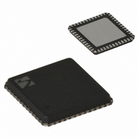
XE1203FI063TRLF Semtech, XE1203FI063TRLF Datasheet - Page 8

XE1203FI063TRLF
Manufacturer Part Number
XE1203FI063TRLF
Description
IC TXRX 433/868/915MHZ 48-VQFN
Manufacturer
Semtech
Specifications of XE1203FI063TRLF
Frequency
180MHz Center
Data Rate - Maximum
152.3kbps
Modulation Or Protocol
FSK
Applications
AMR, ISM, Home Automation, Process Control
Power - Output
0 ~ 15dBm
Sensitivity
-114dBm
Voltage - Supply
2.4 V ~ 3.6 V
Current - Receiving
14mA
Current - Transmitting
62mA
Data Interface
PCB, Surface Mount
Antenna Connector
PCB, Surface Mount
Operating Temperature
-40°C ~ 85°C
Package / Case
48-VQFN
Receiving Current
14mA
Transmitting Current
62mA
Data Rate
152.3Kbps
Modulation Type
FSK
No. Of Pins
48
Supply Voltage Range
2.4V To 3.6V
Operating Temperature Range
-40°C To +85°C
Operating Temperature (min)
-40C
Operating Temperature (max)
85C
Operating Temperature Classification
Industrial
Product Depth (mm)
7mm
Product Length (mm)
7mm
Operating Supply Voltage (typ)
2.5/3.3V
Operating Supply Voltage (max)
3.6V
Lead Free Status / RoHS Status
Lead free / RoHS Compliant
Memory Size
-
Lead Free Status / Rohs Status
Compliant
Other names
XE1203FI063TR
Available stocks
Company
Part Number
Manufacturer
Quantity
Price
Company:
Part Number:
XE1203FI063TRLF
Manufacturer:
SEMTECH
Quantity:
1 100
Company:
Part Number:
XE1203FI063TRLF
Manufacturer:
Semtech
Quantity:
2 300
Part Number:
XE1203FI063TRLF
Manufacturer:
SEMTECH/美国升特
Quantity:
20 000
4.1.1
4.1.2
4.1.3
used to sample the DATA signal without additional external signal processing. In addition, the receiver includes a
digital Received Signal Strength Indicator (RSSI), a Frequency Error Indicator (FEI) that provides information about
the local oscillator frequency error, and a pattern recognition function to detect preprogrammed sequences in the
received serial data stream. Finally, a user-selectable Barker coding/decoding feature can be activated to spread
the outgoing data with an 11-bit Barker code upon transmission and decode the incoming data upon reception by
correlating the spread data with the 11-bit Barker code.
The LNA of the receiver has two programmable operation modes: the high sensitivity mode, Mode A, for reception
of weak signals; and the high linearity mode, Modxe B, for strong signals. The operation mode is defined by the
contents of the SWParam_Rmode1 and SWParam_Rmode2 Configuration Register bits.
The demodulation chain consists of an FSK demodulator, bit synchronizer, Barker decoder and a Pattern
Recognition block. Figure 2 below illustrates the interaction between each section of the demodulation chain.
The demodulator provides a demodulated data stream from the received FSK modulated base band limited
signals, I_lim and Q_lim. If the end-user application requires direct access to the output of the demodulator, then
the RTParam_Bitsync and RTParam_Barker Configuration Register bits are set low (disabled). In this case the
© Semtech 2008
•
•
LNA & Receiver modes
Demodulation chain
Demodulator
Mode A: High sensitivity mode, approximately 13dB better than in Mode B (see 3.2.2, RFS parameter)
Mode B: High Linearity mode, IIP3 approximately 15dB higher than in Mode A (see 3.2.2, IIP3 parameter)
DEMODULATOR
FSK
FSParam_BR
RTParam_Barker
RTParam_Bitsync
pow
pow
SYNCHRONIZER
Figure 2: Demodulation architecture
DECODER
BARKER
BIT
data
dclk
data
8
RTParam_Pattern
dclk
data
ADParam_Psize
ADParam_Pattern
ADParam_Ptol
pow
RECOGNIZER
PATTERN
CONTROL
DATA
pattern
data
dclk
XE1203F
www.semtech.com


