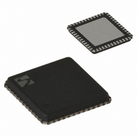
XE1203FI063TRLF Semtech, XE1203FI063TRLF Datasheet - Page 31

XE1203FI063TRLF
Manufacturer Part Number
XE1203FI063TRLF
Description
IC TXRX 433/868/915MHZ 48-VQFN
Manufacturer
Semtech
Specifications of XE1203FI063TRLF
Frequency
180MHz Center
Data Rate - Maximum
152.3kbps
Modulation Or Protocol
FSK
Applications
AMR, ISM, Home Automation, Process Control
Power - Output
0 ~ 15dBm
Sensitivity
-114dBm
Voltage - Supply
2.4 V ~ 3.6 V
Current - Receiving
14mA
Current - Transmitting
62mA
Data Interface
PCB, Surface Mount
Antenna Connector
PCB, Surface Mount
Operating Temperature
-40°C ~ 85°C
Package / Case
48-VQFN
Receiving Current
14mA
Transmitting Current
62mA
Data Rate
152.3Kbps
Modulation Type
FSK
No. Of Pins
48
Supply Voltage Range
2.4V To 3.6V
Operating Temperature Range
-40°C To +85°C
Operating Temperature (min)
-40C
Operating Temperature (max)
85C
Operating Temperature Classification
Industrial
Product Depth (mm)
7mm
Product Length (mm)
7mm
Operating Supply Voltage (typ)
2.5/3.3V
Operating Supply Voltage (max)
3.6V
Lead Free Status / RoHS Status
Lead free / RoHS Compliant
Memory Size
-
Lead Free Status / Rohs Status
Compliant
Other names
XE1203FI063TR
Available stocks
Company
Part Number
Manufacturer
Quantity
Price
Company:
Part Number:
XE1203FI063TRLF
Manufacturer:
SEMTECH
Quantity:
1 100
Company:
Part Number:
XE1203FI063TRLF
Manufacturer:
Semtech
Quantity:
2 300
Part Number:
XE1203FI063TRLF
Manufacturer:
SEMTECH/美国升特
Quantity:
20 000
6.1
6.2
6
This section provides details of the recommended component values for the frequency dependant blocks of the
XE1203F. Note that these values are dependent upon circuit layout and PCB structure, and that decoupling
components have been omitted for clarity.
The schematic of the matching network at the input of the receiver is given below in
impedance of 50Ω).
The typical recommended values for the external components are shown in Table 21:
The optimum load impedances for 15 dBm output power at the three main frequencies are shown in Table 22:
The Smith charts in Figure 20, Figure 21, and Figure 22 below show contours of output power versus load
impedance when the highest transmit level is selected, i.e. 15 dBm:
© Semtech 2008
APPLICATION INFORMATION
RECEIVER MATCHING NETWORK
TRANSMITTER MATCHING NETWORK
Name
CR1
CR2
CR3
LR1
PA optimum load
SOURCE
CR3
Table 22: Optimum load impedances for 15 dBm output power
Table 21: Typical component values for the matching network
Typical Value
for 434 MHz
100 nH
1.5 pF
1.5 pF
NC
Figure 19: Receiver matching network
CR1
CR2
102 – 12j
434 MHz
Typical Value
for 868 MHz
1.5 pF
1.2 pF
27 nH
LR1
NC
31
868 MHz
78 + 19j
Typical Value
for 915 MHz
1.0 pF
1.0 pF
27 nH
RFA
RFB
NC
XE1203
915 MHz
83 + 18j
Tolerance
± 5 %
± 5%
± 5%
± 5%
Figure 19
XE1203F
(for a source
www.semtech.com


