XTOB001CC1 EATON CUTLER HAMMER, XTOB001CC1 Datasheet - Page 121
XTOB001CC1
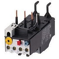
Manufacturer Part Number
XTOB001CC1
Description
Overload Relay
Manufacturer
EATON CUTLER HAMMER
Datasheet
1.XTCE007B10A.pdf
(312 pages)
Specifications of XTOB001CC1
Overload Adjustment Current Min
0.6A
Overload Adjustment Current Max
1A
Coil Voltage Dc Max
220V
Contactor Direction
Non Reversing
Coil Voltage Vdc Nom
220V
Lead Free Status / RoHS Status
Lead free / RoHS Compliant


March 2009
Contents
Description
Catalog Number
Product Selection . . . . . . . . . . 34-125
Accessories . . . . . . . . . . . . . . . 34-130
Technical Data and
Dimensions . . . . . . . . . . . . . . . 34-150
Reference Data . . . . . . . . . . . . 34-210
Product Description
Eaton’s new
Motor Protectors (MMPs) features a
pushbutton or rotary ON/OFF manual
disconnect, Class 10 adjustable
bimetallic overload relay and fixed
magnetic short circuit trip capability in
one compact unit. Two frame sizes
are available: Frame B (45 mm) for
motors with FLA ratings up to 32A
and Frame D (55 mm) covers motor
FLA ratings up to 63A.
Application Description
The XTPB and XTPR MMPs can be
used in the following applications.
Motor Protective Circuit Breaker
In many countries outside of the
United States and Canada, especially
Europe, the MMPs are tested and
classified as thermal magnetic circuit
breakers for use in motor branch
circuits. This can be an important
consideration for all companies who
export their equipment and machines
internationally. Both the XTPB and
XTPR conform to IEC/EN 60947 and
have the CE Mark.
CA08102001E
Selection . . . . . . . . . . . . . . . . 34-124
Specifications . . . . . . . . . . . . 34-142
B-Frame
Pushbutton
B-Frame
Rotary
family of Manual
D-Frame
Page
Manual Motor Protectors
The XTPB and XTPR MMPs are UL Listed
under UL 508 as Manual Motor Protec-
tors. They provide an economical solu-
tion for applications requiring simple
manual starting and stopping of motors.
When used as an MMP, they are typically
installed in an enclosure. Many enclo-
sures are offered as accessories for the
MMPs. Separate short-circuit protective
devices, such as circuit breakers or
fuses, are wired ahead of the MMPs. The
short-circuit protective device should be
sized per the NEC code and should not
exceed 400% of the maximum FLA dial
setting of the MMP.
Group Motor Installations
A Group Motor Installation can be
defined as more than one motor circuit
protected by a single set of fuses or cir-
cuit breaker on a motor branch circuit.
This eliminates the need for individual
fuses or circuit breakers for each
motor circuit. Substantial component
cost savings, panel space savings and
reduced wiring installation time can be
achieved in Group Motor Installations.
The MMPs are tested and listed for
group installation . If remote operation
is required, a magnetic contactor can
be wired in series with the MMP. See
Figure 34-101.
Article 430.53 of the National Electric
Code contains the rules and require-
ments for Group Motor Installations.
Refer to Application Note AP03402001E
for NEC requirement for group motor
installation.
Figure 34-101. Group Motor Installation
NEC 430-53
See Application Note — AP03402001E.
For more information visit: www.eaton.com
To Supply
XTPR
IEC Contactors & Starters
XT IEC Power Control
Manual Motor Protectors
Disconnect
Fuses
XTPR
XTPR
Manual
Motor
Protector
Magnetic Contactor
(Used for
Remote Control)
Motors
Or Circuit
Breaker
Protection in Different
Controller Types
A UL 508 Type E Self-protected Manual
Combination Starter/Motor Controller
consists of a single device having inte-
gral short circuit protection, a main set
of contacts, motor overload protection,
and may also include a UL listed Line
Side Adapter (see Figure 34-102). This
type of controller is a legitimate short
circuit protective device and discon-
nect means for the downstream motor.
It does require an upstream feeder
short circuit protective device, but
does not require a dedicated branch
circuit protection or a disconnect
means. A UL 508 Type E rating means
that the unit clears a fault and does not
experience any welding of the power
poles. A UL 508 Type E self-protected
manual combination starter will
remain fully functional should a short
circuit within its ratings occur.
A UL 508 Type F Self-protected Combi-
nation Motor Controller consists of a
UL 508 Listed Type E Self-protected
Manual Combination Starter/Motor
Controller, a UL Listed Contactor, and
possibly a UL Listed Line Side Adapter.
While the Type E self-protected manual
motor controller of this combination
motor controller device is a legitimate
short circuit protective device and
disconnect means for the down-
stream motor, the contactor is not
“self-protected.” E.g. XTCE007 –
XTCE065.
In addition, as a complete assembly or
modular components, the device should
have Type 2 Coordination certification.
Type 2 Coordination means the Starter or
the Controller must exhibit little or no dam-
age following a major short circuit fault
and should be able to be returned to proper
service without replacing any parts.
Component in a Combination
Motor Controller
The XTPB and XTPR MMPs can also be
wired in series with a magnetic contac-
tor to complete the assembly of a
remotely operated, combination motor
controller.
34-121
34
Related parts for XTOB001CC1
Image
Part Number
Description
Manufacturer
Datasheet
Request
R

Part Number:
Description:
PROGRAMMABLE LOGIC CONTROLLER
Manufacturer:
EATON CUTLER HAMMER
Part Number:
Description:
Pm Power Pro 3000/5000 A-B Accel/On Interface
Manufacturer:
EATON CUTLER HAMMER
Part Number:
Description:
Handle Tie Bar For (2) - 1 Pole Type BR Breakers
Manufacturer:
EATON CUTLER HAMMER
Part Number:
Description:
Type CH Breaker 150A/2 Pole 120/240V 10K
Manufacturer:
EATON CUTLER HAMMER
Part Number:
Description:
Tenant Branch Breaker 125A/3 Pole 120/240V 42K
Manufacturer:
EATON CUTLER HAMMER
Part Number:
Description:
Type CL Breaker 25A/1Pole 120/240V 10K-Classified 1" Ckt Bkr
Manufacturer:
EATON CUTLER HAMMER
Part Number:
Description:
FD BREAKER 1P 80 AMP WITH LOAD ONLY TERMINALS
Manufacturer:
EATON CUTLER HAMMER
Part Number:
Description:
GD 2 POLE BREAKER, 25 AMP, SINGLE PACKED
Manufacturer:
EATON CUTLER HAMMER
Part Number:
Description:
Handle Tie Bar For (2) - 1 Pole Type BR Breakers
Manufacturer:
EATON CUTLER HAMMER
Part Number:
Description:
Type CL Breaker 25A/1Pole 120/240V 10K-Classified 1" Ckt Bkr
Manufacturer:
EATON CUTLER HAMMER