XTOB001CC1 EATON CUTLER HAMMER, XTOB001CC1 Datasheet - Page 250
XTOB001CC1
Manufacturer Part Number
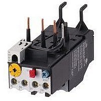
XTOB001CC1
Description
Overload Relay
Manufacturer
EATON CUTLER HAMMER
Datasheet
1.XTCE007B10A.pdf
(312 pages)
Specifications of XTOB001CC1
Overload Adjustment Current Min
0.6A
Overload Adjustment Current Max
1A
Coil Voltage Dc Max
220V
Contactor Direction
Non Reversing
Coil Voltage Vdc Nom
220V
Lead Free Status / RoHS Status
Lead free / RoHS Compliant


34-250
34
Non-reversing and Reversing Contactors (Frame A)
Table 34-301. Approximate Dimensions in Inches (mm)
Non-reversing
Reversing
Figure 34-156. Approximate Dimensions — Inches (mm)
Non-reversing Contactors (Frames B & C)
Table 34-302. Approximate Dimensions in Inches (mm)
Figure 34-157. Approximate Dimensions — Inches (mm)
Frame
Size
A
A
Frame
Size
B
C
(1 L1, 3 L2, 5 L3)
Line Terminals
IEC Contactors & Starters
IT. Electro-Mechanical
Dimensions
Mounting)
(Optional
Standard
(35 x 7.5)
DIN Rail
1.38 x .3
Terminal
Control
Block
Overall
Width
A
1.1
(27)
2.4
(60)
Overall
Width
A
1.8
(45)
2.1
(54)
(Optional Mounting)
E
(1 L1, 3 L2, 5 L3)
Line Terminals
Height
B
3.0
(75)
2.9
(73)
Height
B
4.4
(111)
4.45
(113)
Standard
(35 x 7.5)
1.38 x .3
DIN Rail
P
Q
R
Depth
C
2.4
(60)
2.4
(60)
Depth
C
2.4
(60)
2.4
(60)
E
C
D
Depth w/
Auxiliary
D
3.5
(88)
3.5
(88)
Depth w/
Auxiliary
D
3.6
(91)
3.6
(91)
P
(2 T1, 4 T2, 6 T3)
Load Terminals
Q
R
C
D
Depth added
w/DIN Rail
E
.2
(5)
.2
(5)
Depth added
w/DIN Rail
E
.1
(3)
.1
(3)
Single Auxiliaries
Reduce Dim “D”
For more information visit: www.eaton.com
.28 (7) for the
(2 T1, 4 T2, 6 T3)
Logic Level
Auxiliary –
Load Terminals
Terminal Block
Control
Mounting Holes
Width
F
.76
(19.2)
1.31
(33.2)
Mounting Holes
Width
F
1.33
(33.8)
1.46
(37)
Single Auxiliaries
Reduce Dim “D”
Dual Auxiliary –
.31 (8) for the
B
Height
G
2.64
(67)
2.52
(64)
Height
G
4.0
(101)
4.1
(104)
H
G
Non-reversing
Contactors
Mtg. Hole
to Top
H
.1
(3.5)
.2
(5)
Mtg. Hole
to Top
H
.2
(5)
.2
(5)
A
F
B
K
H
G
(B-Frame Has Two Lower Mtg. Feet,
DIN Rail
to Top
J
.6
(15)
.5
(13)
DIN Rail
to Top
J
.9
(23)
.8
(20)
J
Reference F – Width)
B
C-Frame Pictured
G
Req. Mtg.
Screws
K
(3) #8
M4
(3) #8
M4
Req. Mtg.
Screws
K
(3) #8
M4
(3) #8
M4
A
F
Contactors
Reversing
K
Terminals
Control
P
.6
(16)
.6
(16)
Terminals
Control
P
.7
(19)
.7
(19)
A
F
J
Line
Q
1.7
(43)
1.7
(43)
Line
Q
1.2
(30)
1.2
(30)
CA08102001E
March 2009
K
Load
R
1.7
(43)
1.7
(43)
Load
R
1.2
(30)
1.2
(30)
J
Related parts for XTOB001CC1
Image
Part Number
Description
Manufacturer
Datasheet
Request
R

Part Number:
Description:
PROGRAMMABLE LOGIC CONTROLLER
Manufacturer:
EATON CUTLER HAMMER
Part Number:
Description:
Pm Power Pro 3000/5000 A-B Accel/On Interface
Manufacturer:
EATON CUTLER HAMMER
Part Number:
Description:
Handle Tie Bar For (2) - 1 Pole Type BR Breakers
Manufacturer:
EATON CUTLER HAMMER
Part Number:
Description:
Type CH Breaker 150A/2 Pole 120/240V 10K
Manufacturer:
EATON CUTLER HAMMER
Part Number:
Description:
Tenant Branch Breaker 125A/3 Pole 120/240V 42K
Manufacturer:
EATON CUTLER HAMMER
Part Number:
Description:
Type CL Breaker 25A/1Pole 120/240V 10K-Classified 1" Ckt Bkr
Manufacturer:
EATON CUTLER HAMMER
Part Number:
Description:
FD BREAKER 1P 80 AMP WITH LOAD ONLY TERMINALS
Manufacturer:
EATON CUTLER HAMMER
Part Number:
Description:
GD 2 POLE BREAKER, 25 AMP, SINGLE PACKED
Manufacturer:
EATON CUTLER HAMMER
Part Number:
Description:
Handle Tie Bar For (2) - 1 Pole Type BR Breakers
Manufacturer:
EATON CUTLER HAMMER
Part Number:
Description:
Type CL Breaker 25A/1Pole 120/240V 10K-Classified 1" Ckt Bkr
Manufacturer:
EATON CUTLER HAMMER