XTOB001CC1 EATON CUTLER HAMMER, XTOB001CC1 Datasheet - Page 243
XTOB001CC1
Manufacturer Part Number
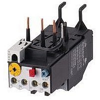
XTOB001CC1
Description
Overload Relay
Manufacturer
EATON CUTLER HAMMER
Datasheet
1.XTCE007B10A.pdf
(312 pages)
Specifications of XTOB001CC1
Overload Adjustment Current Min
0.6A
Overload Adjustment Current Max
1A
Coil Voltage Dc Max
220V
Contactor Direction
Non Reversing
Coil Voltage Vdc Nom
220V
Lead Free Status / RoHS Status
Lead free / RoHS Compliant


March 2009
Electrical Life — AC-1, AC-2, AC-3 and AC-4 Utilization Categories
Table 34-280. Utilization Categories
Life Load Curves — Eaton’s Cutler-
Hammer IT. Electro-Mechanical Series
IEC contactors have been designed
and manufactured for superior life
performance. All testing has been
based on requirements as found in IEC
60947-4-1 and conducted by us. When
selecting a contactor designed to IEC
requirements, the specifier must give
attention to the specific load, utiliza-
tion category and the required electri-
cal life. For a definition of Utilization
Categories, see Table 34-280 above.
Figure 34-148. Electrical Life — AC-3 Utilization Category
Figure 34-149. Electrical Life — AC-4 Utilization Category
CA08102001E
The International Electrotechnical Commission (IEC) has developed utilization categories for contactors and auxiliary contacts. The categories describe the
type of electrical load and the conditions for making and breaking the current.
Category
AC-1
AC-2
AC-3
AC-4
Note: Preliminary data.
Note: Preliminary data.
Plugging is stopping or reversing the motor rapidly by reversing the connections while the motor is running.
Inching or jogging is energizing the motor once or repeatedly for short durations to obtain small movements of the motor driven load.
10,000,000
10,000,000
1,000,000
1,000,000
100,000
100,000
10,000
10,000
Typical Application
Non-inductive or slightly inductive loads: Resistance furnaces, heating.
Slip-ring motors: Starting and stopping of running motors
Squirrel cage motors: Starting, switching off motors during running (motors in most industrial applications typically fall into this cate-
gory).
Squirrel cage motors: Starting, plugging , inching
0.1
1
A
A
B
B
1
6
C
9
Operational Current
Operational Current
10
12
C
D
Frame Size
Frame Size
Note: AC-3 tests are conducted at rated
device currents and AC-4 tests are con-
ducted at six-times rated device currents.
All tests have been run at 460V, 60 Hz.
Actual application life may vary,
depending on environmental condi-
tions and application duty cycle.
18
D E F
6 9
E
For more information visit: www.eaton.com
25 40
IEC Contactors & Starters
IT. Electro-Mechanical
Technical Data and Specifications
10
32
18 32 50 85 125 250
F
50
25 40 65 100 148
65 100 160 250
85 125 200 315
(very few applications in industry are totally AC-4).
320
420
Trip Times
Figure 34-150. Class 10, 20 and 30 Trip Curves
Contactor Choice —
■
■
■
1000.0
Decide what utilization category the
application is and choose the
appropriate curve from Figure 34-
148 or Figure 34-149.
Locate the intersection of the life-
load curve with the operational cur-
rent (le) of the application, as found
on the horizontal axis.
Read the estimated contact life
along the vertical axis in number of
operations.
100.0
10.0
1.0
0.1
1
1
2
3
4
5
6
2
3
Trip Class 10 Cold
Trip Class 10 Hot
Trip Class 20 Cold
Trip Class 20 Hot
Trip Class 30 Cold
Trip Class 30 Hot
Multiples of FLA
4
5
6
7
8
9
10
34-243
5
3
6
1
4
2
34
Related parts for XTOB001CC1
Image
Part Number
Description
Manufacturer
Datasheet
Request
R

Part Number:
Description:
PROGRAMMABLE LOGIC CONTROLLER
Manufacturer:
EATON CUTLER HAMMER
Part Number:
Description:
Pm Power Pro 3000/5000 A-B Accel/On Interface
Manufacturer:
EATON CUTLER HAMMER
Part Number:
Description:
Handle Tie Bar For (2) - 1 Pole Type BR Breakers
Manufacturer:
EATON CUTLER HAMMER
Part Number:
Description:
Type CH Breaker 150A/2 Pole 120/240V 10K
Manufacturer:
EATON CUTLER HAMMER
Part Number:
Description:
Tenant Branch Breaker 125A/3 Pole 120/240V 42K
Manufacturer:
EATON CUTLER HAMMER
Part Number:
Description:
Type CL Breaker 25A/1Pole 120/240V 10K-Classified 1" Ckt Bkr
Manufacturer:
EATON CUTLER HAMMER
Part Number:
Description:
FD BREAKER 1P 80 AMP WITH LOAD ONLY TERMINALS
Manufacturer:
EATON CUTLER HAMMER
Part Number:
Description:
GD 2 POLE BREAKER, 25 AMP, SINGLE PACKED
Manufacturer:
EATON CUTLER HAMMER
Part Number:
Description:
Handle Tie Bar For (2) - 1 Pole Type BR Breakers
Manufacturer:
EATON CUTLER HAMMER
Part Number:
Description:
Type CL Breaker 25A/1Pole 120/240V 10K-Classified 1" Ckt Bkr
Manufacturer:
EATON CUTLER HAMMER