PAXS0010 Red Lion Controls, PAXS0010 Datasheet - Page 11
PAXS0010
Manufacturer Part Number
PAXS0010
Description
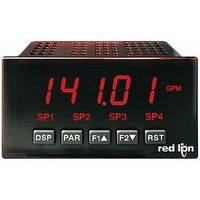
Strain Gauge Meter
Manufacturer
Red Lion Controls
Type
Strain Gager
Specifications of PAXS0010
No. Of Digits / Alpha
5
Meter Function
DC Millivoltmeter
Meter Range
± 24mV To ± 240mV
Digit Height
14.2mm
Power Consumption
11W
Operating Temperature Range
0°C To +50°C
Supply Voltage Dc, Min
11V
Accuracy
0.07% of Reading +4 µV
Brand/series
PAX
Character Height
0.56 in.
Connection Type
2-Wire (Single-Ended), 4-Wire Bridge (Differential)
Cut Out, Panel
1⁄8 DIN
Dimensions
4.2" L × 3.8" W × 1.95" H
Display Digit Height
0.56 "
Display Resolution
1 μV/10 μV
Display Type
LED
Function
Strain Gage
Input Type
Strain Gauge/Bridge Input
Number Of Digits
5
Primary Type
Electronic
Range, Measurement
±24/±240 mvDC
Special Features
Programmable Function Keys
Temperature Range
0 to +50 °C
Temperature, Storage
–40 to +60 °C
Termination
Cage Clamp
Voltage, Input
11-36 VDV, 24 VAC
Lead Free Status / RoHS Status
na


3.2 INPUT SIGNAL WIRING
Resistance Signal
(3 wire requiring
excitation)
Terminal 3: Resistance
Terminal 5: Resistance
Terminal 6: Jumper to
Excitation Jumper:
PAXD INPUT SIGNAL WIRING
PAXP INPUT SIGNAL WIRING
Voltage Signal
Terminal 3: +VDC
Terminal 5: -VDC
Voltage Signal
Terminal 3: +VDC
Terminal 5: -VDC
Before connecting signal wires, the Input Range Jumper and Excitation Jumper should be verified for proper position.
(self powered)
1.75 mA REF.
(self powered)
terminal 3
CAUTION: Sensor input common is NOT isolated from user input common. In order to preserve the safety of the meter application, the sensor input
common must be suitably isolated from hazardous live earth referenced voltages; or input common must be at protective earth ground potential. If not,
hazardous live voltage may be present at the User Inputs and User Input Common terminals. Appropriate considerations must then be given to the
potential of the user input common with respect to earth common; and the common of the isolated plug-in cards with respect to input common.
Current Signal
(self powered)
Terminal 4: +ADC
Terminal 5: -ADC
Current Signal
(self powered)
Terminal 4: +ADC
Terminal 5: -ADC
Current Signal (2 wire
requiring excitation)
Terminal 4: -ADC
Terminal 6: +ADC
Excitation Jumper: 24 V
Current Signal (2 wire
requiring excitation)
Terminal 4: -ADC
Terminal 6: +ADC
11
Potentiometer Signal
(3 wire requiring excitation)
Terminal 3: Wiper
Terminal 5: Low end of pot.
Terminal 6: High end of pot.
Excitation Jumper: 2 V REF.
Input Range Jumper: 2 Volt
Module 1 Input Range: 2 Volt
Note: The Apply signal scaling style
should be used because the signal will
be in volts.
Current Signal (3 wire
requiring excitation)
Terminal 4: +ADC (signal)
Terminal 5: -ADC (common)
Terminal 6: +Volt supply
Excitation Jumper: 24 V
Voltage Signal (3 wire
requiring excitation)
Terminal 3: +VDC (signal)
Terminal 5: -VDC (common)
Terminal 6: +Volt supply
Excitation Jumper: 24 V
Current Signal (3 wire
requiring excitation)
Terminal 4: +ADC (signal)
Terminal 5: -ADC (common)
Terminal 6: +Volt supply
Voltage Signal (3 wire
requiring excitation)
Terminal 3: +VDC (signal)
Terminal 5: -VDC (common)
Terminal 6: +Volt supply
Related parts for PAXS0010
Image
Part Number
Description
Manufacturer
Datasheet
Request
R

Part Number:
Description:
Counter
Manufacturer:
Red Lion Controls
Datasheet:
Part Number:
Description:
Miniature Length Sensor
Manufacturer:
Red Lion Controls
Datasheet:
Part Number:
Description:
Model Lsc - Single Channel Output Length Sensor
Manufacturer:
Red Lion Controls
Datasheet: