PAXS0010 Red Lion Controls, PAXS0010 Datasheet - Page 16
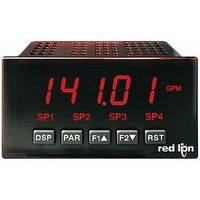
PAXS0010
Manufacturer Part Number
PAXS0010
Description
Strain Gauge Meter
Manufacturer
Red Lion Controls
Type
Strain Gager
Specifications of PAXS0010
No. Of Digits / Alpha
5
Meter Function
DC Millivoltmeter
Meter Range
± 24mV To ± 240mV
Digit Height
14.2mm
Power Consumption
11W
Operating Temperature Range
0°C To +50°C
Supply Voltage Dc, Min
11V
Accuracy
0.07% of Reading +4 µV
Brand/series
PAX
Character Height
0.56 in.
Connection Type
2-Wire (Single-Ended), 4-Wire Bridge (Differential)
Cut Out, Panel
1⁄8 DIN
Dimensions
4.2" L × 3.8" W × 1.95" H
Display Digit Height
0.56 "
Display Resolution
1 μV/10 μV
Display Type
LED
Function
Strain Gage
Input Type
Strain Gauge/Bridge Input
Number Of Digits
5
Primary Type
Electronic
Range, Measurement
±24/±240 mvDC
Special Features
Programmable Function Keys
Temperature Range
0 to +50 °C
Temperature, Storage
–40 to +60 °C
Termination
Cage Clamp
Voltage, Input
11-36 VDV, 24 VAC
Lead Free Status / RoHS Status
na


"
nearest rounding increment selected (ie. rounding of ‘5’ causes 122 to round to
120 and 123 to round to 125). Rounding starts at the least significant digit of
the Input Display. Remaining parameter entries (scaling point values, setpoint
values, etc.) are not automatically adjusted to this display rounding selection.
"
used to compensate for probe errors, errors due to variances in probe placement
or adjusting the readout to a reference thermometer. This value is automatically
updated after a Zero Display to show how far the display is offset. A value of
zero will remove the affects of offset.
"
filter settles to 99% of the final display value within approximately 3 time
constants. This is an Adaptive Digital Filter which is designed to steady the
Input Display reading. A value of ‘0’ disables filtering.
"
variation exceeds the input filter band value, the digital filter disengages. When
the variation becomes less than the band value, the filter engages again. This
allows for a stable readout, but permits the display to settle rapidly after a large
process change. The value of the band is in display units. A band setting of ‘0’
keeps the digital filter permanently engaged.
"
Custom TC range (
automatically compensated by the meter and do not require this setting. To
calculate this slope, use V data obtained from thermocouple manufacturers’
tables for two points between 0 C and 50 C. Place this corresponding V and
a small offset error at room temperatures. This can be compensated by the offset
parameter. A value of 0 disables internal compensation when the thermocouple
is externally compensated.
*
#52;?
)>>:6
>A,6#
PAXT: TEMPERATURE DISPLAY OFFSET*
For the PAXT, the following parameters only apply to Custom
Sensor Scaling.
PAXT: ICE POINT SLOPE
C information into the equation:
Factory Setting can be used without affecting basic start-up.
Rounding selections other than one, cause the Input Display to ‘round’ to the
The temperature display can be corrected with an offset value. This can be
The input filter setting is a time constant expressed in tenths of a second. The
<"$?
The digital filter will adapt to variations in the input signal. When the
This parameter sets the slope value for ice point compensation for the
Due to the nonlinear output of thermocouples, the compensation may show
A(&
-. - -
slope = ( V
3. -
3-
#
#
#
#
#
3
-
(:867
2
DISPLAY ROUNDING*
- V
-. -
-
FILTER SETTING*
83@@@@
-. -
to
FILTER BAND*
) only. The fixed thermocouple ranges are
1
10
to
)/( C
These bottom selections are not
1
%!-. - -
to
/!. -
2
/!. -
available for the PAXT.
- C
to
display units
1
20
@@@@@
2
seconds
).
V/ C
50
5
100
16
"
Linear - Scaling Points (2)
that the 2 scaling points be at opposite ends of the input signal being applied.
The points do not have to be the signal limits. Display scaling will be linear
between and continue past the entered points up to the limits of the Input Signal
Jumper position. Each scaling point has a coordinate-pair of Input Value (
and an associated desired Display Value (
Nonlinear - Scaling Points (Greater than 2)
piece-wise linear approximation. (The greater the number of scaling points
used, the greater the conformity accuracy.) The Input Display will be linear
between scaling points that are sequential in program order. Each scaling point
has a coordinate-pair of Input Value (
Value (
derive the required number of segments and data values for the coordinate pairs.
In the SFPAX software, several linearization equations are available.
must be keyed-in.
"
(
changing of the input signal. If Input Values have to be derived from the actual
input signal source or simulator, the Apply (
After using the Apply (
/$0
"
The Input Range selection sets up the decimal location for the Input Value. With
0.02A Input Range, 4mA would be entered as 4.000. For Apply (
the input signal to the meter, adjust the signal source externally until the desired
Input Value appears. In either method, press the PAR key to enter the value
being displayed.
Note:
scaling display point without storing the input value.
"
the same for
selection.
"
keys. For Apply (
desired Input Value appears. (Follow the same procedure if using more than 2
scaling points.)
:6C,&
4&C
A$+ 3
?:+ 3
A$+ /
For linear processes, only 2 scaling points are necessary. It is recommended
For non-linear processes, up to 16 scaling points may be used to provide a
This parameter does not apply for the PAXT. Scaling values for the PAXT
If Input Values and corresponding Display Values are known, the Key-in
For Key-in (
Enter the first coordinating Display Value by using the arrow keys. This is
For Key-in (
) scaling style can be used. This allows scaling without the presence or
but the scaling values will be shown from the previous applied method.
+6:
3--. - -
"+,C
?:+
4&C
-. - -
-. - -
). Data from tables or equations, or empirical data could be used to
DISPLAY VALUE FOR SCALING POINT 1
style - Pressing the RST key will advance the display to the next
4&C
#
#
#
#
#
INPUT VALUE FOR SCALING POINT 1
INPUT VALUE FOR SCALING POINT 2
/
4&C
4&C
and
), enter the known first Input Value by using the arrow keys.
"+,C
), enter the known second Input Value by using the arrow
"+,C
KEY
APLY
"+,C
), adjust the signal source externally until the next
83@@@@
83@@@@
83@@@@
SCALING POINTS*
/
scaling styles. The decimal point follows the
SCALING STYLE
) scaling style, this parameter will default back to
to
3%
key-in data
apply signal
to
to
to
A$+
@@@@@
@@@@@
@@@@@
?:+
) and an associated desired Display
"+,C
).
) scaling style must be used.
"+,C
), apply
?&(+6
A$+
)
Related parts for PAXS0010
Image
Part Number
Description
Manufacturer
Datasheet
Request
R

Part Number:
Description:
Counter
Manufacturer:
Red Lion Controls
Datasheet:
Part Number:
Description:
Miniature Length Sensor
Manufacturer:
Red Lion Controls
Datasheet:
Part Number:
Description:
Model Lsc - Single Channel Output Length Sensor
Manufacturer:
Red Lion Controls
Datasheet: