PAXS0010 Red Lion Controls, PAXS0010 Datasheet - Page 17
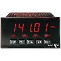
PAXS0010
Manufacturer Part Number
PAXS0010
Description
Strain Gauge Meter
Manufacturer
Red Lion Controls
Type
Strain Gager
Specifications of PAXS0010
No. Of Digits / Alpha
5
Meter Function
DC Millivoltmeter
Meter Range
± 24mV To ± 240mV
Digit Height
14.2mm
Power Consumption
11W
Operating Temperature Range
0°C To +50°C
Supply Voltage Dc, Min
11V
Accuracy
0.07% of Reading +4 µV
Brand/series
PAX
Character Height
0.56 in.
Connection Type
2-Wire (Single-Ended), 4-Wire Bridge (Differential)
Cut Out, Panel
1⁄8 DIN
Dimensions
4.2" L × 3.8" W × 1.95" H
Display Digit Height
0.56 "
Display Resolution
1 μV/10 μV
Display Type
LED
Function
Strain Gage
Input Type
Strain Gauge/Bridge Input
Number Of Digits
5
Primary Type
Electronic
Range, Measurement
±24/±240 mvDC
Special Features
Programmable Function Keys
Temperature Range
0 to +50 °C
Temperature, Storage
–40 to +60 °C
Termination
Cage Clamp
Voltage, Input
11-36 VDV, 24 VAC
Lead Free Status / RoHS Status
na


"
the same for
more than 2 scaling points.)
General Notes on Scaling
1. Input Values for scaling points should be confined to the limits of the Input
2. The same Input Value should not correspond to more than one Display Value.
3. The same Display Value can correspond to more than one Input Value.
meter control functions. While in the Display Mode or Program Mode, the
function is executed the instant the user input transitions to the active state.
specific meter control functions. While in the Display Mode, the primary
function is executed the instant the key is pressed. Holding the function key for
three seconds executes a secondary function. It is possible to program a
secondary function without a primary function.
for the same function, the maintained (level trigger) actions will be performed
while at least one of those user inputs or function keys are activated. The
momentary (edge trigger) actions will be performed every time any of those
user inputs or function keys transition to the active state.
Note:
"
inputs and function keys. No function can be selected without affecting basic
start-up.
"
5.2 MODULE 2 - U
*:#83
*:#83
?:+ /
Enter the second coordinating Display Value by using the arrow keys. This is
Range Jumper position.
(Example: 20 mA can not equal 0 and 10.)
This is referred to as read out jumps (vertical scaled segments).
(Example: 0 mA and 20 mA can equal 10.)
This is referred to as readout dead zones (horizontal scaled segments).
The three user inputs are individually programmable to perform specific
The front panel function keys are also individually programmable to perform
In most cases, if more than one user input and/or function key is programmed
user inputs and front panel function keys. Alternating displays are shown
with each selection. Those selections showing both displays are available for
both. If a display is not shown, it is not available for that selection.
will represent all three user inputs.
No function is performed if activated. This is the factory setting for all user
3--. - -
In the following explanations, not all selections are available for both
+,)(
$)
DISPLAY VALUE FOR SCALING POINT 2
4&C
#
#
#
PROGRAMMING MODE LOCK-OUT
and
(maintained action). A security code can be configured to
allow programming access during lock-out.
"+,C
Programming Mode is locked-out, as long as activated
83@@@@
scaling styles. (Follow the same procedure if using
NO FUNCTION
to
>3
@@@@@
will represent all five function keys.
SER
"
I
PARAMETER MENU
NPUT AND
P
>3
ARAMETERS
*:#83
$)
#
17
4. The maximum scaled Display Value spread between range maximum and
5. For input levels beyond the first programmed Input Value, the meter extends
6. For input levels beyond the last programmed Input Value, the meter extends
"
various input levels, causing future Display readings to be offset. This function
is useful in weighing applications where the container or material on the scale
should not be included in the next measurement value. When activated
(momentary action),
time, the Display value (that was on the display before the Zero Display) is
subtracted from the Display Offset Value and is automatically stored as the new
Display Offset Value (
display will again change to zero and the Display reading will shift accordingly.
"
The Relative is a net value that includes the Display Offset Value. The Input
Display will normally show the Relative unless switched by this function.
Regardless of the display selected, all meter functions continue to operate based
on relative values. The Absolute is a gross value (based on Module 1 DSP and
INP entries) without the Display Offset Value. The Absolute display is selected
as long as the user input is activated (maintained action) or at the transition of
the function key (momentary action). When the user input is released, or the
function key is pressed again, the input display switches back to Relative
display.
to indicate which display is active.
*:#83
*:#83
minimum is limited to 65,535. For example using +20 mA range the
maximum +20 mA can be scaled to is 32,767 with 0 mA being 0 and Display
Rounding of 1. (Decimal points are ignored.) The other half of 65,535 is for
the lower half of the range 0 to -20 mA even if it is not used. With Display
Rounding of 2, +20 mA can be scaled for 65,535 (32,767 x 2) but with even
Input Display values shown.
the Display Value by calculating the slope from the first two coordinate pairs
(
would be some negative Display Value. This could be prevented by making
A$+3
?:+0
the Input Range Jumper position.
the Display Value by calculating the slope from the last two sequential
coordinate pairs. If three coordinate pair scaling points were entered, then the
Display Value calculation would be between
The calculations stop at the limits of the Input Range Jumper position.
The Zero (Tare) Display provides a way to zero the Input Display value at
This function will switch the Input Display between Relative and Absolute.
A$+3
F
?8#&,
RONT
"<:
= the desired high Display Value. The calculations stop at the limits of
= 0 mA /
/
#&,
?:+3
(
(absolute) or
#
#
1"2)3
&
RELATIVE/ABSOLUTE DISPLAY
?:+3
A$+/
P
#&D&6
)EED6
ZERO (TARE) DISPLAY
ANEL
= 0,
/
#&,
?:+/
flashes and the Display is set to zero. At the same
)
). If another Zero (tare) Display is performed, the
A$+/
(relative) is momentarily displayed at transition
). If
= 4 mA /
F
A$+3
UNCTION
= 4 mA and
?:+/
A$+/
= 0, with
/
?:+/
?:+3
"
"
A$+0
&
K
= 0, then 0 mA
A$+0
EY
?8#&,
= 20 mA /
>3
>3
/
#&,
?:+0
#
#
.
Related parts for PAXS0010
Image
Part Number
Description
Manufacturer
Datasheet
Request
R

Part Number:
Description:
Counter
Manufacturer:
Red Lion Controls
Datasheet:
Part Number:
Description:
Miniature Length Sensor
Manufacturer:
Red Lion Controls
Datasheet:
Part Number:
Description:
Model Lsc - Single Channel Output Length Sensor
Manufacturer:
Red Lion Controls
Datasheet: