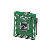
MA160014 Microchip Technology, MA160014 Datasheet - Page 325

MA160014
Manufacturer Part Number
MA160014
Description
MOD PLUG-IN 44PIN PIC18LF45K22
Manufacturer
Microchip Technology
Series
PIC® XLP™ 18Fr
Datasheet
1.PIC18F26J13-ISS.pdf
(496 pages)
Specifications of MA160014
Accessory Type
Plug-In Module (PIM) - PIC18LF45K10
Product
Microcontroller Modules
Data Bus Width
8 bit
Core Processor
PIC18LF45K22
Interface Type
I2C, SPI
Operating Supply Voltage
1.8 V to 5.5 V
Lead Free Status / RoHS Status
Lead free / RoHS Compliant
For Use With/related Products
PICDEM PIC18 Explorer, DM183032
Lead Free Status / Rohs Status
Lead free / RoHS Compliant
Available stocks
Company
Part Number
Manufacturer
Quantity
Price
Company:
Part Number:
MA160014
Manufacturer:
Microchip Technology
Quantity:
135
Company:
Part Number:
MA160014
Manufacturer:
MICROCHIP
Quantity:
12 000
- Current page: 325 of 496
- Download datasheet (5Mb)
19.4
There are two separate methods of measuring
capacitance with the CTMU. The first is the absolute
method, in which the actual capacitance value is
desired. The second is the relative method, in which
the actual capacitance is not needed, rather an
indication of a change in capacitance is required.
19.4.1
For absolute capacitance measurements, both the
current and capacitance calibration steps found in
Section 19.3 “Calibrating the CTMU Module”
should be followed. Capacitance measurements are
then performed using the following steps:
1.
2.
3.
4.
5.
6.
7.
8.
2010 Microchip Technology Inc.
Initialize the A/D Converter.
Initialize the CTMU.
Set EDG1STAT.
Wait for a fixed delay, T.
Clear EDG1STAT.
Perform an A/D conversion.
Calculate the total capacitance, C
where I is known from the current source
measurement step (see
Source
measured by performing an A/D conversion.
Subtract the stray and A/D capacitance
(C
Calibration”) from C
measured capacitance.
OFFSET
Measuring Capacitance with the
CTMU
ABSOLUTE CAPACITANCE
MEASUREMENT
Calibration”), T is a fixed delay and V is
from
Section 19.3.2 “Capacitance
TOTAL
Section 19.3.1 “Current
to determine the
TOTAL
= (I * T)/V,
Preliminary
19.4.2
An application may not require precise capacitance
measurements. For example, when detecting a valid
press of a capacitance-based switch, detecting a rela-
tive change of capacitance is of interest. In this type of
application, when the switch is open (or not touched),
the total capacitance is the capacitance of the combi-
nation of the board traces, the A/D Converter, etc. A
larger voltage will be measured by the A/D Converter.
When the switch is closed (or is touched), the total
capacitance is larger due to the addition of the
capacitance of the human body to the above listed
capacitances, and a smaller voltage will be measured
by the A/D Converter.
Detecting capacitance changes is easily accomplished
with the CTMU using these steps:
1.
2.
3.
4.
5.
The voltage measured by performing the A/D
conversion is an indication of the relative capacitance.
Note that in this case, no calibration of the current
source or circuit capacitance measurement is needed.
See
capacitive touch switch.
PIC18(L)F2X/4XK22
Initialize the A/D Converter and the CTMU.
Set EDG1STAT.
Wait for a fixed delay.
Clear EDG1STAT.
Perform an A/D conversion.
Example 19-4
RELATIVE CHARGE
MEASUREMENT
for a sample software routine for a
DS41412D-page 325
Related parts for MA160014
Image
Part Number
Description
Manufacturer
Datasheet
Request
R

Part Number:
Description:
Manufacturer:
Microchip Technology Inc.
Datasheet:

Part Number:
Description:
Manufacturer:
Microchip Technology Inc.
Datasheet:

Part Number:
Description:
Manufacturer:
Microchip Technology Inc.
Datasheet:

Part Number:
Description:
Manufacturer:
Microchip Technology Inc.
Datasheet:

Part Number:
Description:
Manufacturer:
Microchip Technology Inc.
Datasheet:

Part Number:
Description:
Manufacturer:
Microchip Technology Inc.
Datasheet:

Part Number:
Description:
Manufacturer:
Microchip Technology Inc.
Datasheet:

Part Number:
Description:
Manufacturer:
Microchip Technology Inc.
Datasheet:


