EA-EDU-009 Embedded Artists, EA-EDU-009 Datasheet - Page 12
EA-EDU-009
Manufacturer Part Number
EA-EDU-009
Description
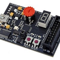
MCU, MPU & DSP Development Tools LPC2103 EDUCATION BRD
Manufacturer
Embedded Artists
Specifications of EA-EDU-009
Processor To Be Evaluated
LPC2103
Data Bus Width
16 bit, 32 bit
Interface Type
I2C, SPI, UART
Core
ARM7TDMI-S
Dimensions
68 mm x 42 mm
Maximum Operating Temperature
+ 85 C
Operating Supply Voltage
3.3 V
Lead Free Status / RoHS Status
Lead free / RoHS Compliant


NXP Semiconductors
LPC2101_02_03_4
Product data sheet
6.5.1 Interrupt sources
6.5 Interrupt controller
6.6 Pin connect block
The VIC accepts all of the interrupt request inputs and categorizes them as FIQ, vectored
IRQ, and non-vectored IRQ as defined by programmable settings. The programmable
assignment scheme means that priorities of interrupts from the various peripherals can be
dynamically assigned and adjusted.
FIQ has the highest priority. If more than one request is assigned to FIQ, the VIC
combines the requests to produce the FIQ signal to the ARM processor. The fastest
possible FIQ latency is achieved when only one request is classified as FIQ, because then
the FIQ service routine does not need to branch into the interrupt service routine but can
run from the interrupt vector location. If more than one request is assigned to the FIQ
class, the FIQ service routine will read a word from the VIC that identifies which FIQ
source(s) is (are) requesting an interrupt.
Vectored IRQs have the middle priority. Sixteen of the interrupt requests can be assigned
to this category. Any of the interrupt requests can be assigned to any of the 16 vectored
IRQ slots, among which slot 0 has the highest priority and slot 15 has the lowest.
Non-vectored IRQs have the lowest priority.
The VIC combines the requests from all the vectored and non-vectored IRQs to produce
the IRQ signal to the ARM processor. The IRQ service routine can start by reading a
register from the VIC and jumping there. If any of the vectored IRQs are pending, the VIC
provides the address of the highest-priority requesting IRQs service routine, otherwise it
provides the address of a default routine that is shared by all the non-vectored IRQs. The
default routine can read another VIC register to see what IRQs are active.
Each peripheral device has one interrupt line connected to the Vectored Interrupt
Controller, but may have several internal interrupt flags. Individual interrupt flags may also
represent more than one interrupt source.
The pin connect block allows selected pins of the microcontroller to have more than one
function. Configuration registers control the multiplexers to allow connection between the
pin and the on chip peripherals. Peripherals should be connected to the appropriate pins
prior to being activated, and prior to any related interrupt(s) being enabled. Activity of any
enabled peripheral function that is not mapped to a related pin should be considered
undefined.
The pin control module with its pin select registers defines the functionality of the
microcontroller in a given hardware environment.
After reset all pins of Port 0 are configured as input with the following exceptions: If the
DBGSEL pin is HIGH (Debug mode enabled), the JTAG pins will assume their JTAG
functionality for use with EmbeddedICE and cannot be configured via the pin connect
block.
Rev. 04 — 2 June 2009
Single-chip 16-bit/32-bit microcontrollers
LPC2101/02/03
© NXP B.V. 2009. All rights reserved.
12 of 37
Related parts for EA-EDU-009
Image
Part Number
Description
Manufacturer
Datasheet
Request
R

Part Number:
Description:
MCU, MPU & DSP Development Tools LPC2148 EDUCATION BRD
Manufacturer:
Embedded Artists
Datasheet:

Part Number:
Description:
MCU, MPU & DSP Development Tools LPC2138 EDUCATION BRD
Manufacturer:
Embedded Artists
Datasheet:

Part Number:
Description:
MCU, MPU & DSP Development Tools EXPERIMENT EXPANSION BRD
Manufacturer:
Embedded Artists
Datasheet:

Part Number:
Description:
HEATSINK FOR TO-220 BLACK
Manufacturer:
Ohmite
Datasheet:

Part Number:
Description:
HEATSINK FOR TO-220 BLACK
Manufacturer:
Ohmite
Datasheet:

Part Number:
Description:
HEATSINK FOR TO-220 BLACK
Manufacturer:
Ohmite
Datasheet:

Part Number:
Description:
LCD Graphic Display Modules & Accessories Pure Green Backlight For DOG-M Series
Manufacturer:
ELECTRONIC ASSEMBLY
Datasheet:

Part Number:
Description:
LCD Graphic Display Modules & Accessories Grn LED Backlight For DOG-XL Series
Manufacturer:
ELECTRONIC ASSEMBLY
Datasheet:
Part Number:
Description:
LCD Graphic Display Modules & Accessories Green LED Backlight For DOG-L Series
Manufacturer:
ELECTRONIC ASSEMBLY
Datasheet:

Part Number:
Description:
KIT LPC3141 SODIMM 66X48 200POS
Manufacturer:
Embedded Artists
Datasheet:
Part Number:
Description:
KIT LPC3152 SODIMM 66X48 200POS
Manufacturer:
Embedded Artists
Datasheet:
Part Number:
Description:
BOARD OEM W/LPC2478 MCU
Manufacturer:
Embedded Artists
Datasheet:
Part Number:
Description:
KIT LPC3250 259 WITH QVGA
Manufacturer:
Embedded Artists
Datasheet: