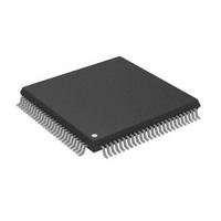
AD9398KSTZ-150 Analog Devices Inc, AD9398KSTZ-150 Datasheet - Page 28

AD9398KSTZ-150
Manufacturer Part Number
AD9398KSTZ-150
Description
IC,TV/VIDEO CIRCUIT,Video Interface Circuit,CMOS,QFP,100PIN,PLASTIC
Manufacturer
Analog Devices Inc
Datasheet
1.AD9398KSTZ-100.pdf
(44 pages)
Specifications of AD9398KSTZ-150
Applications
Video
Interface
HDMI
Voltage - Supply
3.15 V ~ 3.47 V
Package / Case
100-LQFP
Mounting Type
Surface Mount
Lead Free Status / RoHS Status
Lead free / RoHS Compliant
For Use With
AD9398/PCBZ - BOARD EVALUATION FOR AD9398
Lead Free Status / RoHS Status
Lead free / RoHS Compliant
Available stocks
Company
Part Number
Manufacturer
Quantity
Price
Company:
Part Number:
AD9398KSTZ-150
Manufacturer:
AD
Quantity:
5 510
Company:
Part Number:
AD9398KSTZ-150
Manufacturer:
AD
Quantity:
1
Company:
Part Number:
AD9398KSTZ-150
Manufacturer:
Analog Devices Inc
Quantity:
10 000
Part Number:
AD9398KSTZ-150
Manufacturer:
ADI/亚德诺
Quantity:
20 000
AD9398
0x2E—Bit[7] Ctrl Enable
When set, this bit allows Ctrl [3:0] signals decoded from the
DVI to be output on the I
lines. 1 = Ctrl[3:0] output on I
setting is 0.
0x2E—Bits[6:5] I
These bits select between four options for the I
right-justified, left-justified, or raw IEC60958 mode. The
power-up default setting is 00.
Table 15. I
I
00
01
10
11
0x2E—Bits[4:0] I
These bits set the I
power-up default setting is 24 bits.
0x2F—Bit[6] TMDS Sync Detect
This read-only bit indicates the presence of a TMDS DE.
0 = no TMDS DE present. 1 = TMDS DE detected.
0x2F—Bit[5] TMDS Active
This read-only bit indicates the presence of a TMDS clock.
0 = no TMDS clock present. 1 = TMDS clock detected.
0x2F—Bit[4] AV Mute
This read-only bit indicates the presence of AV mute based on
general control packets. 0 = AV not muted. 1 = AV muted.
0x2F—Bit[3] HDCP Keys Read
This read-only bit reports if the HDCP keys were read
successfully. 0 = failure to read HDCP keys. 1 = HDCP keys
read.
0x2F—Bits[2:0] HDMI Quality
These read-only bits indicate a level of HDMI quality based on
the DE (display enable) edges. A larger number indicates a
higher quality.
0x30—Bit[6] HDMI Content Encrypted
This read-only bit is high when HDCP decryption is in use
(content is protected). The signal goes low when HDCP is not
being used. Customers can use this bit to determine whether to
allow copying of the content. The bit should be sampled at
regular intervals because it can change on a frame-by-frame
basis. 0 = HDCP not in use. 1 = HDCP decryption in use.
2
S Output Mode
2
S Output Select
2
2
2
S bit width for right-justified mode. The
S Output Mode
S Bit Width
Result
I
Right-justified
Left-justified
Raw IEC60958 mode
2
S mode
2
S data pins. 0 = I
2
S lines. The power-up default
2
S signals on I
2
S output: I
2
S
2
S,
Rev. 0 | Page 28 of 44
0x30—Bit[5] DVI HSYNC Polarity
This read-only bit indicates the polarity of the DVI HSYNC.
0 = DVI HSYNC polarity is low active. 1 = DVI HSYNC
polarity is high active.
0x30—Bit[4] DVI VSYNC Polarity
This read-only bit indicates the polarity of the DVI VSYNC.
0 = DVI VSYNC polarity is low active. 1 = DVI VSYNC polarity
is high active.
0x30—Bits[3:0] HDMI Pixel Repetition
These read-only bits indicate the pixel repetition on DVI.
0 = 1×, 1 = 2×, 2 = 3×, up to a maximum repetition of
10× (0x9).
Table 16.
Select
0000
0001
0010
0011
0100
0101
0110
0111
1000
1001
MACROVISION
0x31—Bits[7:4] Macrovision Pulse Max
These bits set the pseudo sync pulse width maximum for
Macrovision detection in pixel clocks. This is functional for
13.5 MHz SDTV or 27 MHz progressive scan. Power-up
default is 9.
0x31—Bits[3:0] Macrovision Pulse Min
These bits set the pseudo sync pulse width maximum for
Macrovision detection in pixel clocks. This is functional for
13.5 MHz SDTV or 27 MHz progressive scan. Power-up
default is 6.
0x32—Bit[7] Macrovision Oversample Enable
Tells the Macrovision detection engine whether oversampling
is used. This accommodates 27 MHz sampling for SDTV and
54 MHz sampling for progressive scan and is used as a
correction factor for clock counts. Power-up default is 0.
0x32—Bit[6] Macrovision PAL Enable
Tells the Macrovision detection engine to enter PAL mode when
set to 1. Default is 0 for NTSC mode.
0x32—Bit[5:0] Macrovision Line Count Start
Set the start line for Macrovision detection. Along with
Register 0x33, Bits [5:0], they define the region where MV
pulses are expected to occur. The power-up default is Line 13.
Repetition Multiplier
1×
2×
3×
4×
5×
6×
7×
8×
9×
10×


