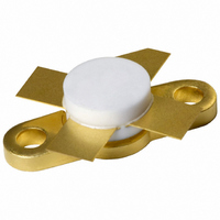
BLF145,112 NXP Semiconductors, BLF145,112 Datasheet - Page 8

BLF145,112
Manufacturer Part Number
BLF145,112
Description
TRANSISTOR RF DMOS SOT123A
Manufacturer
NXP Semiconductors
Datasheet
1.BLF145112.pdf
(15 pages)
Specifications of BLF145,112
Package / Case
SOT-123A
Transistor Type
N-Channel
Frequency
28MHz
Gain
27dB
Voltage - Rated
65V
Current Rating
6A
Current - Test
1.3A
Voltage - Test
28V
Power - Output
8W
Minimum Operating Temperature
- 65 C
Mounting Style
SMD/SMT
Product Type
RF MOSFET Power
Resistance Drain-source Rds (on)
0.75 Ohms
Transistor Polarity
N-Channel
Configuration
Single Dual Source
Drain-source Breakdown Voltage
65 V
Gate-source Breakdown Voltage
+/- 20 V
Continuous Drain Current
6 A
Power Dissipation
68 W
Maximum Operating Temperature
+ 200 C
Application
HF
Channel Type
N
Channel Mode
Enhancement
Drain Source Voltage (max)
65V
Output Power (max)
30W
Power Gain (typ)@vds
27@28V/20@28VdB
Frequency (max)
28MHz
Package Type
SOT-123A
Pin Count
4
Forward Transconductance (typ)
1.2(Min)S
Drain Source Resistance (max)
750@10Vmohm
Input Capacitance (typ)@vds
125@28VpF
Output Capacitance (typ)@vds
75@28VpF
Reverse Capacitance (typ)
7@28VpF
Operating Temp Range
-65C to 200C
Drain Efficiency (typ)
35%
Mounting
Screw
Mode Of Operation
SSB Class-A/SSB Class-AB
Number Of Elements
1
Power Dissipation (max)
68000mW
Vswr (max)
50
Screening Level
Military
Lead Free Status / RoHS Status
Lead free / RoHS Compliant
Noise Figure
-
Lead Free Status / Rohs Status
Compliant
Other names
568-2395
933817070112
BLF145
BLF145
933817070112
BLF145
BLF145
Available stocks
Company
Part Number
Manufacturer
Quantity
Price
Company:
Part Number:
BLF145,112
Manufacturer:
Skyworks
Quantity:
1 400
NXP Semiconductors
List of components (see Fig.11)
Notes
1. American Technical Ceramics (ATC) capacitor, type 100B or other capacitor of the same quality.
2. The striplines are on a double copper-clad printed circuit board, with epoxy dielectric (
handbook, full pagewidth
C1, C3, C8, C9
C2, C10
C4, C7
C5, C6
C11
C12
L1
L2, L3
L4
L5
L6
R1
R2
COMPONENT
HF power MOS transistor
f = 28 MHz.
input
50
film dielectric trimmer
multilayer ceramic chip capacitor; note 1
multilayer ceramic chip capacitor
multilayer ceramic chip capacitor; note 1
multilayer ceramic chip capacitor
electrolytic capacitor
12 turns enamelled 0.5 mm copper wire
stripline; note 2
14 turns enamelled 1 mm copper wire
9 turns enamelled 1 mm copper wire
grade 3B Ferroxcube wideband HF choke
0.25 W metal film resistor
0.25 W metal film resistor
C1
DESCRIPTION
C2
C3
L1
Fig.11 Test circuit for class-A operation.
V G
R1
C4
L2
Rev. 04 - 5 January 2007
D.U.T.
L3
C7
7 to 100 pF
39 pF
100 nF
27 pF
3
2.2 F, 63 V
307 nH
30
1039 nH
305 nH
26
10
L4
VALUE
100 nF
R2
L6
C5
C6
L5
length 8 mm;
int. dia. 4 mm
length 15
length 14 mm;
int. dia. 9 mm
length 10 mm;
int. dia. 6 mm
DIMENSIONS
C11
C8
C10
C9
C12
6 mm
r
V D
= 4.5), thickness 1.6 mm.
MGP042
2222 809 07015
2222 852 47104
2222 852 47104
2222 030 38228
4312 020 36640
Product specification
output
CATALOGUE NO.
50
BLF145
.
8 of 15


