TP3070V-XG National Semiconductor, TP3070V-XG Datasheet - Page 12
TP3070V-XG
Manufacturer Part Number
TP3070V-XG
Description
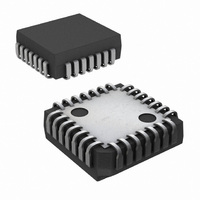
IC COMBO II PCM FILTER 28PLCC
Manufacturer
National Semiconductor
Series
COMBO®IIr
Type
PCM Codec/Filterr
Datasheet
1.TP3070V-GNOPB.pdf
(26 pages)
Specifications of TP3070V-XG
Data Interface
PCM Audio Interface
Number Of Adcs / Dacs
1 / 1
Sigma Delta
No
Voltage - Supply, Analog
±5V
Voltage - Supply, Digital
±5V
Operating Temperature
-40°C ~ 85°C
Mounting Type
Surface Mount
Package / Case
28-LCC (J-Lead)
Lead Free Status / RoHS Status
Contains lead / RoHS non-compliant
Other names
*TP3070V-XG
Available stocks
Company
Part Number
Manufacturer
Quantity
Price
Company:

Part Number:
TP3070V-XG
Manufacturer:
NSC
Quantity:
5 510
Company:
Part Number:
TP3070V-XG
Manufacturer:
Texas Instruments
Quantity:
10 000
Part Number:
TP3070V-XG
Manufacturer:
NS/国半
Quantity:
20 000
Company:
Part Number:
TP3070V-XG/NOPB
Manufacturer:
Texas Instruments
Quantity:
10 000


www.national.com
Symbol
MASTER CLOCK TIMING
f
t
t
t
t
t
t
PCM INTERFACE TIMING
f
t
t
t
t
t
t
t
Symbol
POWER DISSIPATION
I
I
I
MCLK
WMH
WML
RM
FM
HBM
WFL
BCLK
WBH
WBL
RB
FB
HBF
SFB
DBD
BB
CC
BB
Unless otherwise noted, limits printed in BOLD characters are guaranteed for V
+70˚C (−40˚C to +85˚C for TP3070-X) by correlation with 100% electrical testing at T
correlation with other production tests and/or product design and characterization. All signals referenced to GND. Typicals
specified at V
All timing parameters are measured at V
See Definitions and Timing Conventions section for test methods information.
Electrical Characteristics
Unless otherwise noted, limits printed in BOLD characters are guaranteed for V
+70˚C (−40˚C to +85˚C for TP3070-X) by correlation with 100% electrical testing at T
correlation with other production tests and/or product design and characterization. All signals referenced to GND. Typicals
specified at V
Note 9: “Absolute Maximum Ratings” indicate limits beyond which damage to the device may occur. Operating Ratings indicate conditions for which the device is
functional, but do not guarantee specific performance limits.
Note 10: See definitions and timing conventions section.
Timing Specifications
1
2
2
Power Up Current
Power Down Current
Power Down Current
Frequency of MCLK
Period of MCLK High
Period of MCLK Low
Rise Time of MCLK
Fall Time of MCLK
HOLD Time, BCLK LOW
to MCLK HIGH
Period of F
Frequency of BCLK
Period of BCLK High
Period of BCLK Low
Rise Time of BCLK
Fall Time of BCLK
Hold Time, BCLK Low
to FS
Setup Time, FS
High to BCLK Low
Delay Time, BCLK High
to Data Valid
CC
CC
Parameter
X/R
= +5V, V
= +5V, V
High or Low
Parameter
SX
or F
BB
X/R
BB
SR
= −5V, T
= −5V, T
Low
As Above
−40˚C to +85˚C (TP3070-X)
Power Amp Enabled
−40˚C to +85˚C (TP3070-X)
Power Amp Enabled
−40˚C to +85˚C (TP3070-X)
A
A
= 25˚C.
OH
= 25˚C.
(Continued)
= 2.0V and V
Selection of Frequency is
Programmable (See Table 5 )
Measured from V
Measured from V
Measured from V
Measured from V
TP3070 Only
Measured from V
May Vary from 64 kHz to 4096 kHz
in 8 kHz Increments
Measured from V
Measured from V
Measured from V
Measured from V
Load = 100 pF Plus 2 LSTTL Loads
−40˚C to +85˚C (TP3070-X)
Conditions
OL
Conditions
= 0.7V.
12
IH
IL
IL
IH
IL
IH
IL
IL
IH
to V
to V
to V
to V
to V
to V
to V
to V
to V
IL
IH
IL
IL
IH
IH
IL
IH
IL
(Note 11)
(Note 11)
CC
CC
= +5V
= +5V
A
A
= 25˚C. All other limits are assured by
Min
= 25˚C. All other limits are assured by
80
80
50
64
80
80
30
30
1
±
±
5%; V
5%, V
1536
1544
2048
4096
Typ
512
Min
BB
BB
= −5V
= −5V
4096
−8.0
−2.0
Max
Typ
2.0
±
30
30
30
30
80
90
±
5%; T
5%; T
−11.0
−13.0
A
Max
−3.0
−4.0
MCLK Period
A
4.0
3.0
= 0˚C to
= 0˚C to
Units
kHz
kHz
kHz
kHz
kHz
kHz
ns
ns
ns
ns
ns
ns
ns
ns
ns
ns
ns
ns
ns
Units
mA
mA
mA
mA
mA
mA
Related parts for TP3070V-XG
Image
Part Number
Description
Manufacturer
Datasheet
Request
R

Part Number:
Description:
IC INTERFAC PCM COMBO II 28-PLCC
Manufacturer:
National Semiconductor
Datasheet:

Part Number:
Description:
IC COMBO II EXT.TEMP. 28PLCC
Manufacturer:
National Semiconductor
Datasheet:

Part Number:
Description:
Audio CODEC IC
Manufacturer:
National Semiconductor
Datasheet:

Part Number:
Description:
Manufacturer:
National Semiconductor
Datasheet:
Part Number:
Description:
IC,PCM CODEC,SINGLE,CMOS,LDCC,28PIN,PLASTIC
Manufacturer:
National Semiconductor

Part Number:
Description:
Combo Ii Programmable Pcm Codec/filter
Manufacturer:
National Semiconductor Corporation
Datasheet:

Part Number:
Description:
TRISILTM
Manufacturer:
STMicroelectronics
Datasheet:
Part Number:
Description:
National Semiconductor [8-Bit D/A Converter]
Manufacturer:
National Semiconductor
Datasheet:
Part Number:
Description:
National Semiconductor [Media Coprocessor]
Manufacturer:
National Semiconductor
Datasheet:
Part Number:
Description:
Digitally Controlled Tone and Volume Circuit with Stereo Audio Power Amplifier, Microphone Preamp Stage and National 3D Sound
Manufacturer:
National Semiconductor
Datasheet: