TP3070V-XG National Semiconductor, TP3070V-XG Datasheet - Page 8
TP3070V-XG
Manufacturer Part Number
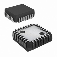
TP3070V-XG
Description
IC COMBO II PCM FILTER 28PLCC
Manufacturer
National Semiconductor
Series
COMBO®IIr
Type
PCM Codec/Filterr
Datasheet
1.TP3070V-GNOPB.pdf
(26 pages)
Specifications of TP3070V-XG
Data Interface
PCM Audio Interface
Number Of Adcs / Dacs
1 / 1
Sigma Delta
No
Voltage - Supply, Analog
±5V
Voltage - Supply, Digital
±5V
Operating Temperature
-40°C ~ 85°C
Mounting Type
Surface Mount
Package / Case
28-LCC (J-Lead)
Lead Free Status / RoHS Status
Contains lead / RoHS non-compliant
Other names
*TP3070V-XG
Available stocks
Company
Part Number
Manufacturer
Quantity
Price
Company:

Part Number:
TP3070V-XG
Manufacturer:
NSC
Quantity:
5 510
Company:
Part Number:
TP3070V-XG
Manufacturer:
Texas Instruments
Quantity:
10 000
Part Number:
TP3070V-XG
Manufacturer:
NS/国半
Quantity:
20 000
Company:
Part Number:
TP3070V-XG/NOPB
Manufacturer:
Texas Instruments
Quantity:
10 000


www.national.com
Programmable Functions
and convert to the binary equivalent. Some examples are
given in Table 7 and a complete tabulation is given in Appen-
dix I of AN-614.
It should be noted that the Transmit (idle channel) Noise and
Transmit Signal to Total Distortion are both specified with
transmit gain set to 0 dB (Gain Register set to all ones). At
high transmit gains there will be some degradation in noise
performance for these parameters. See Application Note
AN-614 for more information on this subject.
Note 8: Analog signal path is cut off, but D
codes representing idle noise.
8.0 RECEIVE GAIN INSTRUCTION BYTE 2
The receive gain can be programmed in 0.1 dB steps by writ-
ing to the Receive Gain Register as defined in Table 1 and
Table 8 . Note the following restrictions on output drive capa-
bility:
a) 0 dBm0 levels
b) 0 dBm0 levels
c) 0 dBm0 levels
To calculate the binary code for byte 2 of this instruction for
any desired output 0 dBm0 level in Vrms, take the nearest in-
teger to the decimal number given by:
and convert to the binary equivalent. Some examples are
given in Table 8 and a complete tabulation is given in Appen-
dix I of AN-614.
9.0 HYBRID BALANCE FILTER
The Hybrid Balance Filter on COMBO II is a programmable
filter consisting of a second-order section, Hybal1, followed
by a first-order section, Hybal2, and a programmable attenu-
a load of
Register set to all ones)
a load of
a load of
7 6 5 4 3 2 1 0
0 0 0 0 0 0 0 0
0 0 0 0 0 0 0 1
0 0 0 0 0 0 1 0
1 1 1 1 1 1 1 0
1 1 1 1 1 1 1 1
7 6 5 4 3 2 1 0
0 0 0 0 0 0 0 0
0 0 0 0 0 0 0 1
0 0 0 0 0 0 1 0
1 1 1 1 1 1 1 0
1 1 1 1 1 1 1 1
TABLE 7. Byte 2 of Transmit Gain Instruction
Bit Number
TABLE 8. Byte 2 of Receive Gain Instruction
Bit Number
—
—
15 k to GND; receive gain set to 0 dB (Gain
600
300
200 x log
1.96 Vrms at VF
1.85 Vrms at VF
1.71 Vrms at VF
to GND; receive gain set to −0.5 dB
to GND; receive gain set to −1.2 dB
10
0 dBm0 Test Level (Vrms)
0 dBm0 Test Level (Vrms)
No Output (Low Z to GND)
(V/0.1043)
No Output (Note 8)
X
remains active and will output
R
R
R
at VF
at VF
O may be driven into
O may be driven into
O may be driven into
0.087
0.088
1.600
1.619
0.105
0.107
1.941
1.964
—
—
R
(Continued)
X
O
I
8
ator. Either of the filter sections can be bypassed if only one
is required to achieve good cancellation. A selectable 180
degree inverting stage is included to compensate for inter-
face circuits which also invert the transmit input relative to
the receive output signal. The 2nd order section is intended
mainly to balance low frequency signals across a trans-
former SLIC, and the first order section to balance midrange
to higher audio frequency signals.
As a 2nd order section, Hybal1 has a pair of low frequency
zeroes and a pair of complex conjugate poles. When config-
uring Hybal1, matching the phase of the hybrid at low to
mid-band frequencies is most critical. Once the echo path is
correctly balanced in phase, the magnitude of the cancella-
tion signal can be corrected by the programmable attenua-
tor.
The 2nd order mode of Hybal1 is most suitable for balancing
interfaces with transformers having high inductance of 1.5
Henries or more. An alternative configuration for smaller
transformers is available by converting Hybal1 to a simple
first-order section with a single real low-frequency pole and
zero. In this mode, the pole/zero frequency may be pro-
grammed.
Many line interfaces can be adequately balanced by use of
the Hybal1 section only, in which case the Hybal2 filter
should be de-selected to bypass it.
Hybal2, the higher frequency first-order section, is provided
for balancing an electronic SLIC, and is also helpful with a
transformer SLIC in providing additional phase correction for
mid and high-band frequencies, typically 1 kHz to 3.4 kHz.
Such a correction is particularly useful if the test balance im-
pedance includes a capacitor of 100 nF or less, such as the
loaded and non-loaded loop test networks in the United
States. Independent placement of the pole and zero location
is provided.
Figure 2 shows a simplified diagram of the local echo path
for a typical application with a transformer interface. The
magnitude and phase of the local echo signal, measured at
VF
transformer and the impedance of the 2W loop, Z
pedance reflected back into the transformer primary is ex-
pressed as Z
VF
9.1 PROGRAMMING THE FILTER
On initial power-up, the Hybrid Balance filter is disabled. Be-
fore the hybrid balance filter can be programmed it is neces-
sary to design the transformer and termination impedance in
order to meet system 2W input return loss specifications,
which are normally measured against a fixed test impedance
(600 or 900
path be modeled and the hybrid balance filter programmed.
Hybrid balancing is also measured against a fixed test im-
pedance, specified by each national Telecom administration
to provide adequate control of talker and listener echo over
the majority of their network connections. This test imped-
ance is Z
transhybrid loss obtained by the programmable filter must be
measured from the PCM digital input, D
tal output, D
conversion back to analog by a PCM CODEC/Filter.
X
R
I, are a function of the termination impedance Z
O to VF
L
in Figure 2 . The echo signal and the degree of
X
X
I is:
L
0, either by digital test signal analysis or by
' then the echo path transfer function from
in most countries). Only then can the echo
H(w) = Z
L
'/(Z
T
+ Z
L
')
R
0, to the PCM digi-
L
. If the im-
T
, the line
(1)
Related parts for TP3070V-XG
Image
Part Number
Description
Manufacturer
Datasheet
Request
R

Part Number:
Description:
IC INTERFAC PCM COMBO II 28-PLCC
Manufacturer:
National Semiconductor
Datasheet:

Part Number:
Description:
IC COMBO II EXT.TEMP. 28PLCC
Manufacturer:
National Semiconductor
Datasheet:

Part Number:
Description:
Audio CODEC IC
Manufacturer:
National Semiconductor
Datasheet:

Part Number:
Description:
Manufacturer:
National Semiconductor
Datasheet:
Part Number:
Description:
IC,PCM CODEC,SINGLE,CMOS,LDCC,28PIN,PLASTIC
Manufacturer:
National Semiconductor

Part Number:
Description:
Combo Ii Programmable Pcm Codec/filter
Manufacturer:
National Semiconductor Corporation
Datasheet:

Part Number:
Description:
TRISILTM
Manufacturer:
STMicroelectronics
Datasheet:
Part Number:
Description:
National Semiconductor [8-Bit D/A Converter]
Manufacturer:
National Semiconductor
Datasheet:
Part Number:
Description:
National Semiconductor [Media Coprocessor]
Manufacturer:
National Semiconductor
Datasheet:
Part Number:
Description:
Digitally Controlled Tone and Volume Circuit with Stereo Audio Power Amplifier, Microphone Preamp Stage and National 3D Sound
Manufacturer:
National Semiconductor
Datasheet: