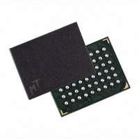
MT45W4MW16BFB-706 WT TR Micron Technology Inc, MT45W4MW16BFB-706 WT TR Datasheet - Page 7

MT45W4MW16BFB-706 WT TR
Manufacturer Part Number
MT45W4MW16BFB-706 WT TR
Description
IC PSRAM 64MBIT 70NS 54VFBGA
Manufacturer
Micron Technology Inc
Datasheet
1.MT45W4MW16BBB-706_WT_TR.pdf
(61 pages)
Specifications of MT45W4MW16BFB-706 WT TR
Format - Memory
RAM
Memory Type
PSRAM (Page)
Memory Size
64M (4M x 16)
Speed
70ns
Interface
Parallel
Voltage - Supply
1.7 V ~ 1.95 V
Operating Temperature
-30°C ~ 85°C
Package / Case
54-VFBGA
Lead Free Status / RoHS Status
Contains lead / RoHS non-compliant
Bus Operations
Table 2:
Table 3:
PDF: 09005aef80be1fbd/Source: 09005aef80be2036
Burst CellularRAM_2.fm - Rev. G 10/05 EN
Mode
Mode
Read
Write
Standby
No Operation
Configuration
Register
DPD
Async Read
Async Write
Standby
No Operation
Initial Burst
Read
Initial Burst
Write
Burst
Continue
Burst Suspend
Configuration
Register
DPD
Bus Operations – Asynchronous Mode
Bus Operations – Burst Mode
Power-Down
Power-Down
Standby
Standby
Power
Power
Active
Active
Active
Active
Active
Active
Active
Active
Active
Active
Deep
Deep
Notes: 1. CLK may be HIGH or LOW, but must be static, during async read and async write modes
Idle
Idle
2. The WAIT polarity is configured through the bus configuration register (BCR[10]).
3. When LB# and UB# are in select mode (LOW), DQ[15:0] are affected. When only LB# is in
4. The device will consume active power in this mode whenever addresses are changed.
5. When the device is in standby mode, address inputs and data inputs/outputs are internally
6. V
7. DPD is maintained until RCR is reconfigured.
8. Burst mode operation is initialized through the bus configuration register (BCR[15]).
and to achieve standby and DPD modes. CLK must be static (HIGH or LOW) during burst
suspend.
select mode, DQ[7:0] are affected. When only UB# is in the select mode, DQ[15:8] are
affected.
isolated from any external influence.
current.
IN
CLK
CLK
= V
64Mb: 4 Meg x 16 Async/Page/Burst CellularRAM 1.0 Memory
X
X
X
X
X
X
X
X
X
X
X
X
CC
1
1
Q or 0V; all device balls must be static (unswitched) in order to achieve standby
ADV#
ADV#
X
X
X
X
X
H
X
X
L
L
L
L
L
L
L
L
CE#
CE#
H
H
H
H
L
L
L
L
L
L
L
L
L
L
L
L
7
OE#
OE#
X
X
H
X
X
X
X
X
X
H
X
H
H
X
L
L
WE#
WE#
Micron Technology, Inc., reserves the right to change products or specifications without notice.
H
X
X
X
H
X
X
H
X
X
X
L
L
L
L
L
CRE
CRE
H
X
H
L
L
L
L
X
X
L
L
L
L
L
L
L
LB#/
UB#
LB#/
UB#
X
X
X
X
L
L
X
X
X
X
X
X
L
L
L
L
WAIT
High-Z
High-Z
Low-Z
Low-Z
Low-Z
Low-Z
WAIT
High-Z
High-Z
Low-Z
Low-Z
Low-Z
Low-Z
Low-Z
Low-Z
Low-Z
Low-Z
©2003 Micron Technology, Inc. All rights reserved.
2
2
Bus Operations
DQ[15:0]
DQ[15:0]
Data-In or
Data-Out
Data-Out
Data-Out
Data-Out
Data-In
Data-In
Data-In
High-Z
High-Z
High-Z
High-Z
High-Z
High-Z
High-Z
X
X
3
3
Notes
Notes
5, 6
4, 6
5, 6
4, 6
4, 8
4, 8
4, 8
4, 8
4
4
7
4
4
8
7


