FAN4802LNY Fairchild Semiconductor, FAN4802LNY Datasheet - Page 18
FAN4802LNY
Manufacturer Part Number
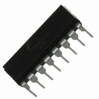
FAN4802LNY
Description
IC PFC CTRLR AVERAGE CURR 16DIP
Manufacturer
Fairchild Semiconductor
Specifications of FAN4802LNY
Mode
Average Current
Frequency - Switching
64kHz
Current - Startup
30µA
Voltage - Supply
11 V ~ 22 V
Operating Temperature
-40°C ~ 105°C
Mounting Type
Through Hole
Package / Case
16-DIP (0.300", 7.62mm)
Operating Temperature (max)
105C
Operating Temperature (min)
-40C
Pin Count
16
Mounting
Through Hole
Screening Level
Industrial
Lead Free Status / RoHS Status
Lead free / RoHS Compliant


© 2008 Fairchild Semiconductor Corporation
FAN4800A/C, FAN4801/02/02L • Rev. 1.0.3
Functional Description
The FAN4800A/C and FAN4801/02/02L consist of an
average current controlled, continuous boost Power
Factor Correction (PFC) front-end and a synchronized
Pulse Width Modulator (PWM) back-end. The PWM can
be used in current or voltage mode. In voltage mode,
feed forward from the PFC output bus can be used to
improve the line regulation of PWM. In either mode, the
PWM stage uses conventional trailing-edge, duty-cycle
modulation.
modulation results in a higher usable PFC error
amplifier bandwidth and can significantly reduce the
size of the PFC DC bus capacitor.
The synchronization of the PWM with the PFC simplifies
the PWM compensation due to the controlled ripple on
the PFC output capacitor (the PWM input capacitor).
The PWM section of the FAN4800A, FAN4801/1S
operates at the same frequency as the PFC; and
FAN4800C, FAN4802/2L operates at double with PFC.
In addition to power factor correction, a number of
protection features are built into this series. They
include soft-start, PFC over-voltage protection, peak
current limiting, brownout protection, duty cycle limiting,
and under-voltage lockout (UVLO).
Gain Modulator
The gain modulator is the heart of the PFC, as the
circuit block controls the response of the current loop to
line voltage waveform and frequency, RMS line voltage,
and PFC output voltages. There are three inputs to the
gain modulator:
1. A current representing the instantaneous input
2. A voltage proportional to the long-term RMS AC line
3. The output of the voltage error amplifier, VEA. The
The output of the gain modulator is a current signal, in
the form of a full wave rectified sinusoid at twice the line
frequency. This current is applied to the virtual ground
(negative) input of the current error amplifier. In this way,
the gain modulator forms the reference for the current
error loop and ultimately controls the instantaneous
current draw of the PFC from the power line. The
general form of the output of the gain modulator is:
voltage (amplitude and wave shape) to the PFC. The
rectified AC input sine wave is converted to a
proportional current via a resistor and is fed into the
gain modulator at IAC. Sampling current in this way
minimizes ground noise, required in high-power,
switching-power conversion environments. The gain
modulator responds linearly to this current.
voltage, derived from the rectified line voltage after
scaling and filtering. This signal is presented to the
gain modulator at VRMS. The output of the gain
modulator is inversely proportional to VRMS (except
at unusually low values of V
contouring takes over to limit power dissipation of the
circuit components under brownout conditions).
gain modulator responds linearly to variations in this
voltage.
This
propriety
RMS
leading/trailing
, where special gain
edge
18
Note that the output current of the gain modulator is
limited around 159μA and the maximum output voltage
of the gain modulator is limited to 159μA x 5.7K=0.906V.
This 0.906V also determines the maximum input power.
However, I
ISENSE. ISENSE
be measured when VEA is less than 0.5V and I
is 0A. Typical I
Selecting R
The IAC pin is the input of the gain modulator and also
a current mirror input and requires current input.
Selecting a proper resistor R
wave current derived from the line voltage and helps
program the maximum input power and minimum input
line voltage. R
minimum line voltage is 75V
56KΩ=6MΩ.
Current Amplifier Error, IEA
The current error amplifier’s output controls the PFC
duty cycle to keep the average current through the
boost inductor a linear function of the line voltage. At
the inverting input to the current error amplifier, the
output current of the gain modulator is summed with a
current, which results in a negative voltage being
impressed upon the ISENSE pin.
The negative voltage on ISENSE represents the sum of
all currents flowing in the PFC circuit and is typically
derived from a current sense resistor in series with the
negative terminal of the input bridge rectifier.
The inverting input of the current error amplifier is a
virtual ground. Given this fact, and the arrangement of
the duty cycle modulator polarities internal to the PFC,
an increase in positive current from the gain modulator
causes the output stage to increase its duty cycle until
the voltage on ISENSE is adequately negative to cancel
this increased current. Similarly, if the gain modulator’s
output decreases, the output duty cycle decreases to
achieve a less negative voltage on the ISENSE pin.
PFC Cycle-By-Cycle Current Limiter
As well as being a part of the current feedback loop, the
ISENSE pin is a direct input to the cycle-by-cycle
current limiter for the PFC section. If the input voltage at
this pin is less than -1.15V, the output of the PFC is
disabled until the protection flip-flop is reset by the clock
pulse at the start of the next PFC power cycle.
I
GAINMOD
GAINMOD
IAC
OFFSET
AC
AC
=
VRMS
=
V
for IAC Pin
(
I
VEA
IN
GAINMOD
cannot be measured directly from
peak x 56KΩ. For example, if the
is around 31μA ~ 48μA.
2
0.7)
– I
OFFSET
AC
AC
, the R
K
provides a good sine
and I
AC
OFFSET
=
75 x 1.414 x
www.fairchildsemi.com
can only
GAINMOD
(1)
Related parts for FAN4802LNY
Image
Part Number
Description
Manufacturer
Datasheet
Request
R

Part Number:
Description:
Fairchild Semiconductor [IGBT MODULE]
Manufacturer:
Fairchild Semiconductor
Datasheet:

Part Number:
Description:
Discrete Semiconductor Modules
Manufacturer:
Fairchild Semiconductor
Part Number:
Description:
Discrete Semiconductor Modules
Manufacturer:
Fairchild Semiconductor
Part Number:
Description:
This N-Channel MOSFET is produced using Fairchild Semiconductor’s advanced Power Trench® process
Manufacturer:
Fairchild Semiconductor
Datasheet:
Part Number:
Description:
This N-Channel MOSFET is produced using Fairchild Semiconductor’s advanced Power Trench® process
Manufacturer:
Fairchild Semiconductor
Datasheet:
Part Number:
Description:
This N-Channel MOSFET is produced using Fairchild Semiconductor’s advanced PowerTrench® process
Manufacturer:
Fairchild Semiconductor
Datasheet:
Part Number:
Description:
This N-Channel MOSFET is produced using Fairchild Semiconductor’s advanced PowerTrench® process
Manufacturer:
Fairchild Semiconductor
Datasheet:
Part Number:
Description:
This N-Channel MOSFET is produced using Fairchild Semiconductor’s advanced Power Trench® process
Manufacturer:
Fairchild Semiconductor
Datasheet:
Part Number:
Description:
This N-Channel logic Level MOSFETs are produced using Fairchild Semiconductor‘s advanced Power Trench® process that has been special tailored to minimize the on-state resistance and yet maintain superior switching performance
Manufacturer:
Fairchild Semiconductor
Datasheet:
Part Number:
Description:
This N-Channel MOSFET is produced using Fairchild Semiconductor’s advanced Power Trench® process
Manufacturer:
Fairchild Semiconductor
Datasheet:
Part Number:
Description:
This N-Channel SyncFET™ is produced using Fairchild Semiconductor’s advanced PowerTrench® process
Manufacturer:
Fairchild Semiconductor
Datasheet:
Part Number:
Description:
This N-Channel SyncFET™ is produced using Fairchild Semiconductor’s advanced PowerTrench® process
Manufacturer:
Fairchild Semiconductor
Datasheet:
Part Number:
Description:
This N-Channel SyncFET™ is produced using Fairchild Semiconductor’s advanced PowerTrench® process
Manufacturer:
Fairchild Semiconductor
Datasheet:
Part Number:
Description:
This N-Channel logic Level MOSFETs are produced using Fairchild Semiconductor‘s advanced Power Trench® process that has been special tailored to minimize the on-state resistance and yet maintain superior switching performance
Manufacturer:
Fairchild Semiconductor
Datasheet:
Part Number:
Description:
This N-Channel MOSFET is produced using Fairchild Semiconductor’s advanced Power Trench® process that has been especially tailored to minimize the on-state resistance and yet maintain superior switching performance
Manufacturer:
Fairchild Semiconductor
Datasheet: