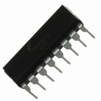
FAN4802LNY Fairchild Semiconductor, FAN4802LNY Datasheet - Page 7

FAN4802LNY
Manufacturer Part Number
FAN4802LNY
Description
IC PFC CTRLR AVERAGE CURR 16DIP
Manufacturer
Fairchild Semiconductor
Specifications of FAN4802LNY
Mode
Average Current
Frequency - Switching
64kHz
Current - Startup
30µA
Voltage - Supply
11 V ~ 22 V
Operating Temperature
-40°C ~ 105°C
Mounting Type
Through Hole
Package / Case
16-DIP (0.300", 7.62mm)
Operating Temperature (max)
105C
Operating Temperature (min)
-40C
Pin Count
16
Mounting
Through Hole
Screening Level
Industrial
Lead Free Status / RoHS Status
Lead free / RoHS Compliant
© 2008 Fairchild Semiconductor Corporation
FAN4800A/C, FAN4801/02/02L • Rev. 1.0.3
Pin Configuration
Pin Definitions
Pin #
10
11
12
13
14
15
16
1
2
3
4
5
6
7
8
9
ISENSE
FBPWM
OPWM
FBPFC
Name
RT/CT
VRMS
RAMP
ILIMIT
OPFC
VREF
GND
VDD
VEA
IEA
IAC
SS
Output of PFC Current Amplifier. The signal from this pin is compared with an internal
sawtooth to determine the pulse width for PFC gate drive.
Input AC Current. For normal operation, this input provides current reference for the multiplier.
The suggested maximum IAC is 100µA.
PFC Current Sense. The non-inverting input of the PFC current amplifier and the output of
multiplier and PFC ILIMIT comparator.
Line-Voltage Detection. Line voltage detection. The pin is used for PFC multiplier.
PWM Soft-Start. During startup, the SS pin charges an external capacitor with a 10µA constant
current source. The voltage on FBPWM is clamped by SS during startup. In the event of a
protection condition occurring and/or PWM disabled, the SS pin is quickly discharged.
PWM Feedback Input. The control input for voltage-loop feedback of PWM stage.
Oscillator RC Timing Connection. Oscillator timing node; timing set by R
PWM RAMP Input. In current mode, this pin functions as the current sense input; when in
voltage mode, it is the feed forward sense input from PFC output 380V (feedforward ramp).
Peak Current Limit Setting for PWM. The peak current limits setting for PWM.
Ground.
PWM Gate Drive. The totem-pole output drive for PWM MOSFET. This pin is internally
clamped under 15V to protect the MOSFET.
PFC Gate Drive. The totem pole output drive for PWM MOSFET. This pin is internally clamped
under 15V to protect the MOSFET.
Supply. The power supply pin. The threshold voltages for startup and turn-off are 11V and
9.3V, respectively. The operating current is lower than 10mA.
Reference Voltage. Buffered output for the internal 7.5V reference.
Voltage Feedback Input for PFC. The feedback input for PFC voltage loop. The inverting input
of PFC error amplifier. This pin is connected to the PFC output through a divider network.
Output of PFC Voltage Amplifier. The error amplifier output for PFC voltage feedback loop.
A compensation network is connected between this pin and ground.
Figure 7. Pin Configuration (Top View)
7
Description
T
and C
T
.
www.fairchildsemi.com


