ISL6551IR-T Intersil, ISL6551IR-T Datasheet - Page 16

ISL6551IR-T
Manufacturer Part Number
ISL6551IR-T
Description
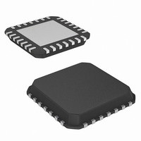
IC CTRL PWM ZVS FULL BRDG 28-QFN
Manufacturer
Intersil
Datasheet
1.ISL6551IBZ.pdf
(26 pages)
Specifications of ISL6551IR-T
Pwm Type
Current Mode
Number Of Outputs
6
Frequency - Max
1MHz
Duty Cycle
50%
Voltage - Supply
10.8 V ~ 13.2 V
Buck
No
Boost
No
Flyback
Yes
Inverting
No
Doubler
No
Divider
No
Cuk
No
Isolated
No
Operating Temperature
0°C ~ 85°C
Package / Case
28-VQFN Exposed Pad, 28-HVQFN, 28-SQFN, 28-DHVQFN
Frequency-max
1MHz
Lead Free Status / RoHS Status
Contains lead / RoHS non-compliant
Additional Applications Information
Table 1 highlights parameter setting for the ISL6551.
Designers can use this table as a design checklist. For
VDD = 12V at room temperature, unless otherwise stated.
Frequency
Dead Time
Resonant Delay
Ramp Adjust
Current Sense
Peak Current
Bandgap Reference
Leading Edge Blanking
Current Share Compensation
Soft-Start & Output Rise Time
Clamp Voltage (Vclamp)
Error Amplifier
Share Support
Latching Shutdown
Power Good
IC Enable
Reference Ground
Power Ground
Upper Drivers
Lower Drivers
Synchronous Drive Signals
Bias for Control Circuits
Biases for Bridge Drivers
PARAMETER
16
LOWER1, LOWER2 Capacitive load up to 1.6nF at Fsw = 500kHz
UPPER1, UPPER2 Capacitive load up to 1.6nF at Fsw = 500kHz
EANI, EAI, EAO
SYNC1, SYNC2
VDDP1, VDDP2
R_RESDLY
PIN NAME
CS_COMP
ON/OFF
ISENSE
BGREF
SHARE
PKILIM
R_LEB
LATSD
DCOK
PGND
R_RA
TABLE 1. PARAMETER SETTING HIGHLIGHTS/CHECKLIST
CSS
VDD
CSS
VSS
CT
RD
Set 50% Duty Cycle Pulses with a fixed frequency
DT = M x RD/kΩ, where M = 11.4
t
Vramp = BGREF/(R_RA x 500E-12) x dt
<Vclamp-200mV-Vramp
<BGREF and slightly higher than Vclamp
1.263V ±2%, 399kΩ pull-up, No more than 100µA load
t
0.1µ for a low current loop bandwidth (100 - 500Hz)
t
Vclamp = Iss x Rcss, or Reference-based clamp
EANI, EAO < Vclamp
30K load & a resistor (1K, typ.) between EANI and OUTPUT REF.
Latch IC off at > 3V
±5% with hysteresis, Sink up to 5mA, transient rejection
Turn on/off at TTL level
Connect to PGND in only one single point
Single point to VSS plane
Capacitive load up to 20pF at Fsw = 500kHz
12V ±10%, 0.1µF decoupling capacitor
Need decoupling capacitors
RESDLY
LEB
ss
= Vclamp x Css/Iss, t
= 2 x R_LEB/kΩ + 15, never leave it floating
= 4.01 x R_RESDLY/kΩ + 13
ISL6551
FORMULA OR SETTING HIGHLIGHT
detailed operation of the ISL6551, see Block/Pin Functional
Descriptions.
rise
= EANI x CSS / Iss, Iss = 10µA ±20%
UNIT
kHz
Hz
ns
ns
ns
V
V
V
V
S
V
V
V
V
V
V
V
-
-
-
-
-
-
January 3, 2006
FIGURE #
11, 12
1, 2
8, 9
4, 5
10
3
7
6
4
FN9066.5
-
-
-
-
-
-
-
-
-
-
-
-
-
-


