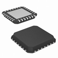
ISL6551IR-T Intersil, ISL6551IR-T Datasheet - Page 21

ISL6551IR-T
Manufacturer Part Number
ISL6551IR-T
Description
IC CTRL PWM ZVS FULL BRDG 28-QFN
Manufacturer
Intersil
Datasheet
1.ISL6551IBZ.pdf
(26 pages)
Specifications of ISL6551IR-T
Pwm Type
Current Mode
Number Of Outputs
6
Frequency - Max
1MHz
Duty Cycle
50%
Voltage - Supply
10.8 V ~ 13.2 V
Buck
No
Boost
No
Flyback
Yes
Inverting
No
Doubler
No
Divider
No
Cuk
No
Isolated
No
Operating Temperature
0°C ~ 85°C
Package / Case
28-VQFN Exposed Pad, 28-HVQFN, 28-SQFN, 28-DHVQFN
Frequency-max
1MHz
Lead Free Status / RoHS Status
Contains lead / RoHS non-compliant
Output Filter
Current Doubler Filter - Two inductors are needed, but they
can be integrated and coupled into one core. Each inductor
carries half of the load operating at the switching frequency.
Conventional Filter - One inductor is needed. The inductor
carries all the load operating at two times the switching
frequency.
Controller
ISL6551 Controller - It can be used as a full bridge or push-
pull PWM controller. The QFN package requires less space
than the SOIC package.
OUTPUT
REFERENCE
(BDAC)
EAO
EAI
S+
S–
R_RESDLY
CS_COMP
FIGURE 20A. CURRENT DOUBLER FILTER
V
OUT
ISENSE
BGREF
FIGURE 20B. CONVENTIONAL FILTER
PKILIM
R_LEB
R_RA
EANI
EAO
VSS
CSS
F
FIGURE 21. ISL6551 CONTROLLER
EAI
RD
CT
10
11
12
13
14
1
2
3
4
5
6
7
8
9
L
F
L
ICL6551
OUT
CLOCK
OUT
SOIC
21
28
27
26
25
24
23
22
21
20
19
18
17
16
15
VDD
VDDP1
VDDP2
PGND
UPPER1
UPPER2
LOWER1
LOWER2
SYNC1
SYNC2
ON / OFF
DCOK
LSTSD
SHARE
C
OUT
V
OUT
C
OUT
LSTSD
VOUT
UV & OV
INPUT
LED
SHARE
BUS
ISL6551
Secondary Drivers
Inverting Drivers - Inverting the SYNC signals or the
LOWER signals with external high current drivers to drive
the synchronous FETs.
Non-inverting Drivers - Cascading SYNC signals with non-
inverting high current drivers to drive the synchronous FETs.
There is a dead time between SYNC1 and SYNC2. For a
higher efficiency, schottky diodes are normally in parallel
with the synchronous FETs to reduce the conduction losses
during the dead time in high output current applications.
Primary Control - This requires a pulse transformer,
operating at the switching frequency, for isolation. There are
three options to drive the synchronous FETs, as described in
previous lines.
SYNC2
/LOWER1
SYNC1
SYN2
SYN1
SYN1
SYN2
IC
MIC4422BM
MIC4421BM
FIGURE 22B. NON-INVERTING DRIVERS
F
T_SYN
IN OUT
SW
IN
GND
FIGURE 22A. INVERTING DRIVERS
FIGURE 22C. PRIMARY CONTROL
GND
OUT
SYNC2/LOWER1
SYNC1/LOWER2
MIC4421BM
SYNP
INVERTING
SYNP
SYNC1
SYNC2
MIC4422BM
SYNC1
/LOWER2
SYNC2
NON INVERTING
IN OUT
IN OUT
GND
GND
MIC4421BM
MIC4422BM
IN OUT
IN
GND
GND
OUT
SYNN
SYNP
January 3, 2006
SYNN
SYNN
FN9066.5


