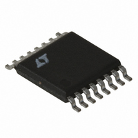
LT3837EFE#TRPBF Linear Technology, LT3837EFE#TRPBF Datasheet - Page 15

LT3837EFE#TRPBF
Manufacturer Part Number
LT3837EFE#TRPBF
Description
IC CNTRLR SYNC ISO 16TSSOP
Manufacturer
Linear Technology
Type
Flybackr
Datasheet
1.LT3837EFETRPBF.pdf
(28 pages)
Specifications of LT3837EFE#TRPBF
Internal Switch(s)
No
Synchronous Rectifier
Yes
Number Of Outputs
1
Frequency - Switching
50kHz ~ 250kHz
Voltage - Input
4.5 ~ 20 V
Operating Temperature
-40°C ~ 125°C
Mounting Type
Surface Mount
Package / Case
16-TSSOP Exposed Pad, 16-eTSSOP, 16-HTSSOP
Lead Free Status / RoHS Status
Lead free / RoHS Compliant
Current - Output
-
Voltage - Output
-
Power - Output
-
Available stocks
Company
Part Number
Manufacturer
Quantity
Price
APPLICATIONS INFORMATION
tight coupling usually increases primary-to-secondary
capacitance and limits the primary-to-secondary break-
down voltage, so it isn’t always practical.
Primary Inductance
The transformer primary inductance, L
on the peak-to-peak ripple current ratio (X) in the trans-
former relative to its maximum value. As a general rule,
keep X in the range of 50% to 70% ripple current (i.e., X =
0.5 to 0.7). Higher values of ripple will increase conduction
losses, while lower values will require larger cores.
Ripple current and percentage ripple is largest at minimum
duty cycle; in other words, at the highest input voltage.
L
where:
Continuing with the 9V to 3.3V example, let us assume a
10A output, 9V to 18V input power with 88% effi ciency.
Using X = 0.7, and f
Optimization might show that a more effi cient solution
is obtained at higher peak current but lower inductance
and the associated winding series resistance. A simple
spreadsheet program is useful for looking at tradeoffs.
P
f
DC
X
L
P
DC
L
is calculated from:
OSC
IN
MAX
P
P
MIN
MIN
=
=
=
is the OSC frequency
(
200
is ripple current ratio at maximum input voltage
3 3 10
V
is the DC at maximum input voltage
.
=
f
IN MAX
OSC
88
(
1
(
•
kHz
18
+
%
•
V
N V
X
A
• .
)
• .
•
MAX
0
•
0 355
=
V
1
DC
7 7 37 5
OSC
IN MAX
OUT
37 5
•
(
MIN
•
.
P
= 200kHz:
)
IN
W
2
.
)
)
2
W
= =
=
1
=
(
+
V
7 8
IN MAX
3
1
.
f
OSC
(
1
•
μ
3 3
H
18
P
.
, is selected based
•
)
X
•
=
MAX
D D C
35 5
MIN
. %
•
P
OUT
)
2
•
Eff
Transformer Core Selection
Once L
High effi ciency converters use ferrite cores to minimize
core loss. Actual core loss is independent of core size for
a fi xed inductance, but decreases as inductance increases.
Since increased inductance is accomplished through
more turns of wire, copper losses increase. Thus trans-
former design balances core and copper losses. Remem-
ber that increased winding resistance will degrade cross
regulation and increase the amount of load compensa-
tion required.
The main design goals for core selection are reducing
copper losses and preventing saturation. Ferrite core mate-
rial saturates hard, rapidly reducing inductance when the
peak design current is exceeded. This results in an abrupt
increase in inductor ripple current and, consequently, out-
put voltage ripple. Do not allow the core to saturate! The
maximum peak primary current occurs at minimum V
Using the example numbers leads to:
Multiple Outputs
One advantage that the fl yback topology offers is that ad-
ditional output voltages can be obtained simply by adding
windings. Designing a transformer for such a situation is
beyond the scope of this document. For multiple windings,
realize that the fl yback winding signal is a combination of
activity on all the secondary windings. Thus load regulation
is affected by each windings load. Take care to minimize
cross regulation effects.
I
DC
now
X
PK
MIN
I
MA
PK
=
:
X X
=
V
=
=
P
IN MIN
=
(
0 380
9
(
V
is known, the type of transformer is selected.
.
1
V
I I N MIN
37 5
+
f
OSC
• .
(
P
)
.
N V
0 524
IN
•
W
•
DC
)
•
V
1
L
•
OUT
IN MIN
MAX
DC
P
(
•
•
⎛
⎝ ⎜
MAX
P
1
IN
•
)
+
⎛
⎝ ⎜
=
1
)
0 380
2
+
1
.
2
+
=
X
3
200 z z
1
MIN
2
1
⎞
⎠ ⎟
•
=
3 3
kH
⎞
⎠ ⎟
9
.
9 47
.
(
=
9 0 52
• .
52 4
• .
7 8
A
LT3837
. %
μ
H
)
•
2
37 5
15
.
3837fc
W
IN
:


